Flow control valve and cooling circuit for vehicles with flow control valve

a technology of flow control valve and cooling circuit, which is applied in the direction of machines/engines, mechanical equipment, cylinders, etc., can solve the problems of difficult application of the integrated flow control valve, poor fuel efficiency of the vehicle at the initial cold start condition, and degraded combustion stability, so as to achieve optimal adaptability, rapid warming of the engine, and simplified cooling lines

Active Publication Date: 2019-06-20
HYUNDAI MOTOR CO LTD +1
View PDF8 Cites 1 Cited by
  • Summary
  • Abstract
  • Description
  • Claims
  • Application Information

AI Technical Summary

Benefits of technology

[0028]According to an exemplary embodiment of the present invention, in the V-type engine, the cooling water is introduced into the flow control valve after being joined together at a front side of the flow control valve, simplifying a cooling line between the cylinder head and the flow control valve, and having an effect of optimally adapting the flow control valve to the cooling circuit of the V-type engine.
[0029]Furthermore, with a single operation of the flow control valve, the three ports are variably controlled, implementing variable temperature control elevating the entire of an engine, and rapid warming up of the engine, maximizing fuel efficiency improvement.
[0030]Furthermore, various control stages are provided in the flow control valve according to an operating condition of a vehicle, and the operation is controlled through sequential control stages, having an effect of reducing operating distance and times of the flow control valve,
[0031]Furthermore, setting of the heating-first stage enables a flow rate toward the heater core to be maximized, eliminating unnecessary flow loss of cooling water and maximizing the fuel efficiency and heating performance.

Problems solved by technology

Generally, a vehicle has poor fuel efficiency at its initial cold start condition, compared to at its sufficiently warmed-up condition.
This is because friction in an engine is great due to high viscosity of low temperature oil during cold operation, and heat loss through cold temperature cylinder wall is great, whereby combustion stability becomes degraded.
However, in the case of a vehicle having a V-type engine, a cooling line is complicated, making it difficult to apply the integrated flow control valve thereto, and thus there is a demand for a cooling circuit capable of applying the integrated flow control valve to the V-type engine.

Method used


Image

  • Flow control valve and cooling circuit for vehicles with flow control valve
  • Flow control valve and cooling circuit for vehicles with flow control valve
  • Flow control valve and cooling circuit for vehicles with flow control valve

Examples


Embodiment Construction

[0042]Reference will now be made in detail to various embodiments of the present invention(s), examples of which are illustrated in the accompanying drawings and described below. While the invention(s) will be described in conjunction with exemplary embodiments, it will be understood that the present description is not intended to limit the invention(s) to those exemplary embodiments. On the other hand, the invention(s) is / are intended to cover not only the exemplary embodiments, but also various alternatives, modifications, equivalents and other embodiments, which may be included within the spirit and scope of the invention as defined by the appended claims.

[0043]Hereinbelow, exemplary embodiments of the present invention will be described in detail with reference to the accompanying drawings.

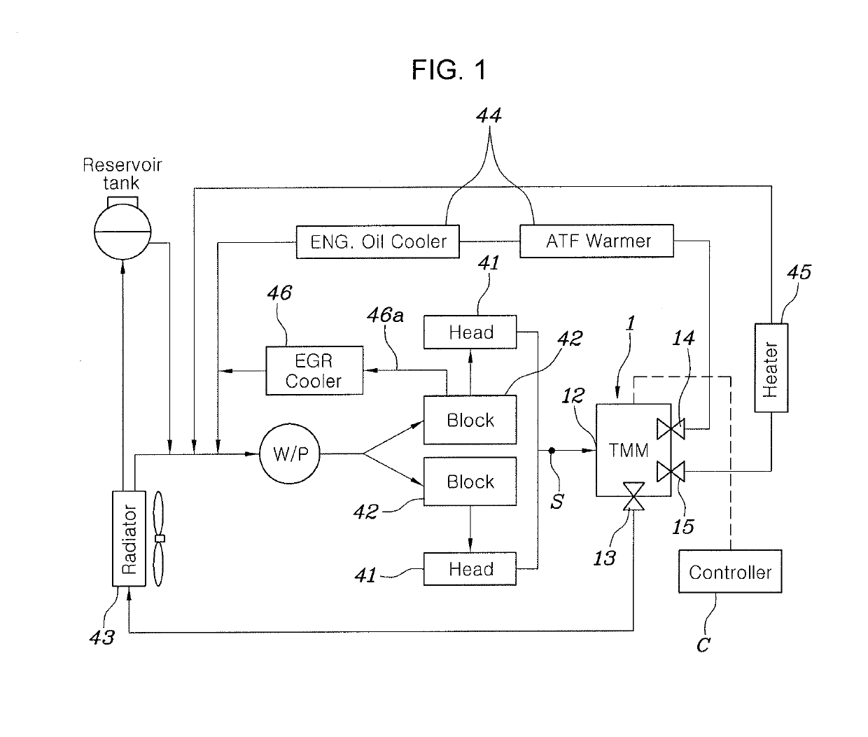
[0044]FIG. 1 is a schematic view illustrating the configuration of a cooling circuit for a vehicle, wherein a flow control valve 1 according to an exemplary embodiment of the present invention...


PUM


Abstract

A cooling circuit for a vehicle may include a plurality of cylinder heads into which cooling water is continuously introduced from a plurality of cylinder blocks oppositely disposed parallel with each other, wherein a flow control valve may include a head port, through which the cooling water discharged from the plurality of cylinder heads is joined and the joined cooling water is introduced into the flow control valve, and wherein the flow control valve also may include a set of ports including a radiator port, a heat exchanger port, and a heater core port, through which the cooling water introduced into the flow control valve is discharged towards a radiator, an oil heat exchanger, and a heater core, respectively.

Description

CROSS REFERENCE TO RELATED APPLICATION(S)[0001]The present application claims priority to Korean Patent Application No. 10-2017-0174860, filed on Dec. 19, 2017, the entire contents of which is incorporated herein for all purposes by this reference.BACKGROUND OF THE INVENTIONField of the Invention[0002]The present invention relates generally to a flow control valve and a cooling circuit for a vehicle, wherein the cooling circuit has an optimized flow control valve in an engine having a complex cooling circuit, such as a V-type engine.Description of Related Art[0003]Generally, a vehicle has poor fuel efficiency at its initial cold start condition, compared to at its sufficiently warmed-up condition. This is because friction in an engine is great due to high viscosity of low temperature oil during cold operation, and heat loss through cold temperature cylinder wall is great, whereby combustion stability becomes degraded.[0004]Thus, it is required to rapidly elevate temperature of an en...

Claims


Application Information

Patent Timeline
Patent Type & Authority Applications(United States)
IPC IPC(8): F02F1/14F02M26/13F02F1/36
CPCF02F1/14F02M26/13F02F1/36F01P3/02F01P2060/04F01P2060/045F01P2060/18F01P7/165F01P2025/32Y02T10/12F01P3/20F01P7/14F02M26/22F16J15/025F16K5/0457F01P2007/146
Inventor LEE, PHIL GIPARK, JAE SUKKIM, SEONG SOO
Owner HYUNDAI MOTOR CO LTD
Why Eureka
Try Eureka