
Array substrate and display panel

a display panel and substrate technology, applied in the field of display technology, to achieve the effect of improving the homogeneity of displaying the display panel, and increasing the capacitance of the storage capacitor

Active Publication Date: 2019-06-20
SHENZHEN CHINA STAR OPTOELECTRONICS TECH CO LTD
View PDF2 Cites 0 Cited by
  • Summary
  • Abstract
  • Description
  • Claims
  • Application Information

AI Technical Summary

Benefits of technology

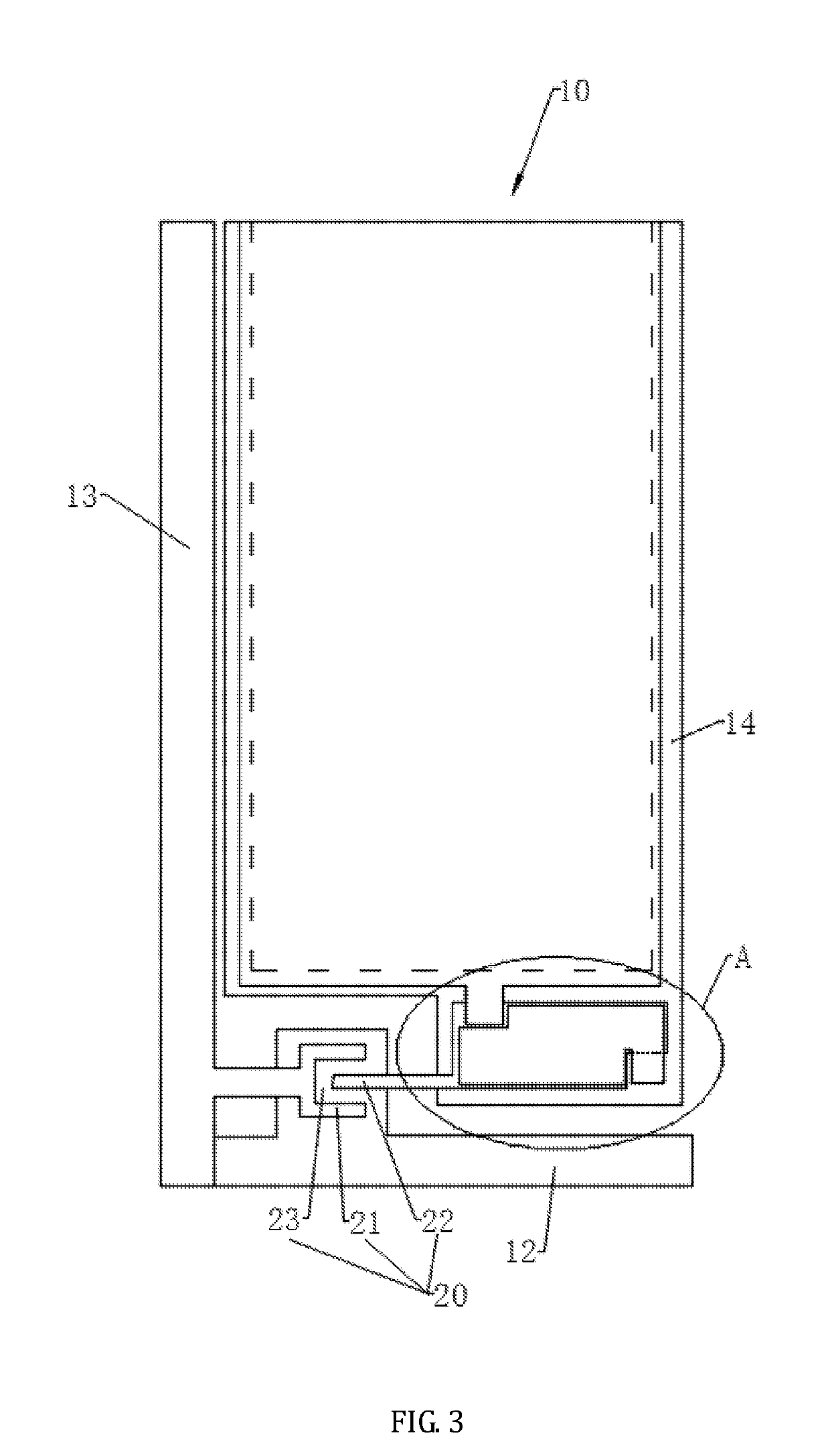
The present invention provides an array substrate for a display panel that increases the capacitance of the storage capacitor, which improves the homogeneity of displaying and prevents abnormalities, such as image sticking. This is achieved by using the sub pixel electrode and the common electrode to form the two electrode plates of the storage capacitor, increasing the total confronting area between them. Additionally, a conductor plate is provided to further increase the capacitance of the storage capacitor.

Problems solved by technology

It is a challenge of this industry to increase the storage capacitance in order to reduce the kickback voltage.

Method used

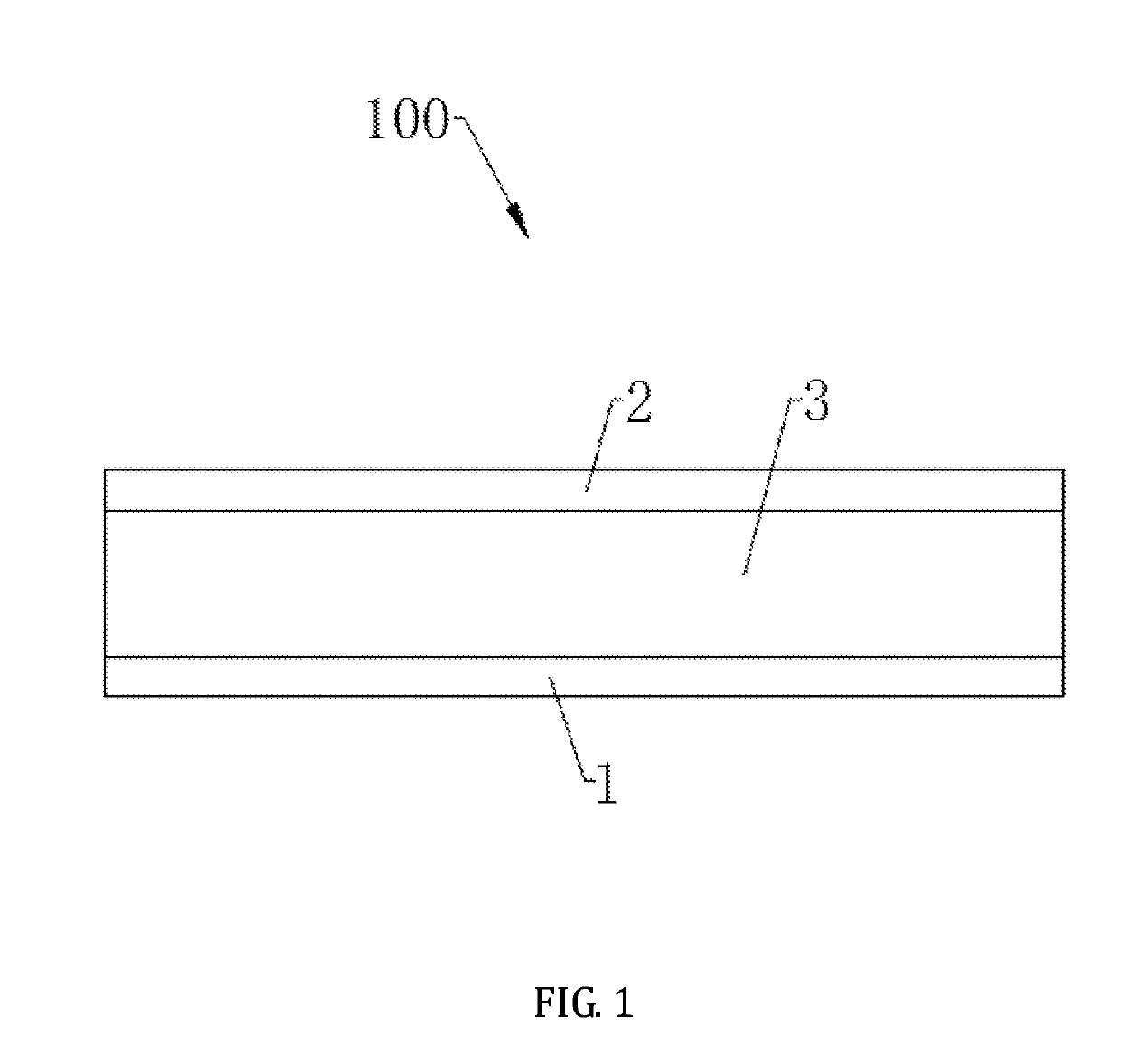
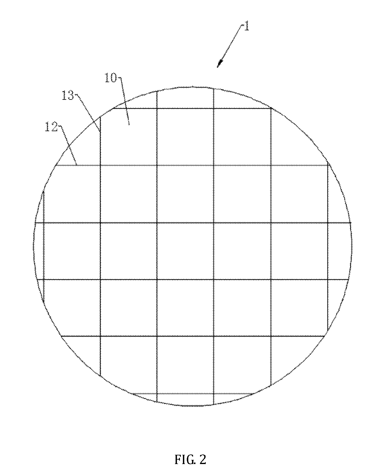

Image

  • Array substrate and display panel
  • Array substrate and display panel
  • Array substrate and display panel

Examples


Embodiment Construction

[0028]A description will be given to technical solutions provided by embodiments of the present invention with reference to the attached drawings of the embodiments of the present invention. However, the embodiments so described are only some, but not all, of the embodiments of the present invention. Other embodiments that are available to those having ordinary skills of the art based on the embodiment of the present invention, without the expense of creative effort and endeavor, are considered belonging to the scope of protection of the present invention.

[0029]In addition, the description given below for each embodiment is made with reference to the attached drawings to exemplify specific embodiments that the present invention may be put into practice. Direction related terminology used in the present invention, such as “up”, “down”, “front”, “rear”, “left”, “right”, “internal”, “external”, and “lateral”, is provided as direction defined in the drawing sheets. Thus, using the direc...


PUM

PropertyMeasurementUnit
areaaaaaaaaaaa
kickback voltage ΔVaaaaaaaaaa
voltageaaaaaaaaaa

Abstract

An array substrate includes a plurality of pixel units arranged in an array. Each of the pixel units includes a common electrode, a first insulation layer, a sub pixel electrode, a second insulation layer, and a conductor plate that are sequentially stacked. The conductor plate is electrically connected to the common electrode. The common electrode and the sub pixel electrode collectively form therebetween a first confronting area and the conductor plate and the sub pixel electrode collectively form therebetween a second confronting area, such that a storage capacitor is formed, collectively, between the common electrode and the sub pixel electrode and between the conductor plate and the sub pixel electrode. The above-described array substrate provides a relatively large storage capacitor. Also disclosed is a display panel.

Description

CROSS REFERENCE TO RELATED APPLICATIONS[0001]This is a continuation application of co-pending U.S. patent application Ser. No. 15 / 736,315, filed on Dec. 14, 2017, which is a national stage of PCT Application No. PCT / CN2017 / 110002, filed on Nov. 8, 2017, claiming foreign priority of Chinese Patent Application No. 201710848747.6 filed on Sep. 18, 2017, titled “Array Substrate and Display Panel”, the disclosure of which is incorporated herein by reference in its entirety.BACKGROUND OF THE INVENTION1. Field of the Invention[0002]The present invention relates to the field of display technology, and more particularly to an array substrate and a display panel.2. The Related Arts[0003]The liquid crystal display panel industry has been developed for decades. The vertical alignment (VA) display mode is a common display mode of thin-film transistor liquid crystal displays (TFT-LCDs) for large-scale televisions due to advantages including wide view angle, high contrast, and requiring no rubbing...

Claims


Application Information

Patent Timeline
Patent Type & Authority Applications(United States)
IPC IPC(8): H01L27/12G02F1/1368G02F1/1362
CPCH01L27/124G02F1/1368G02F1/136213G02F2201/121G02F2201/123G02F2001/136222H01L27/1255G02F1/136222
Inventor AN, LIYANG
Owner SHENZHEN CHINA STAR OPTOELECTRONICS TECH CO LTD
Learn More