
Laser-induced micro-anchor structural and passivation layer for metal-polymeric composite joining and methods for manufacturing thereof

a technology of metal-polymer composite and passivation layer, which is applied in the field of metal-polymer composite joint, can solve the problems of difficult or infeasible molding of large parts, difficulty in manufacturing certain components, and difficulty in manufacturing large parts from reinforced composite materials, and achieve the highest laser fluence, facilitate the formation of aluminum oxide (al2o3) passivation layer, and facilitate the effect of forming large-scale components

Inactive Publication Date: 2019-06-27
GM GLOBAL TECH OPERATIONS LLC
View PDF2 Cites 2 Cited by
  • Summary
  • Abstract
  • Description
  • Claims
  • Application Information

AI Technical Summary

Benefits of technology

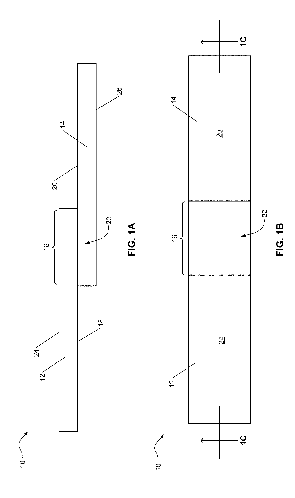
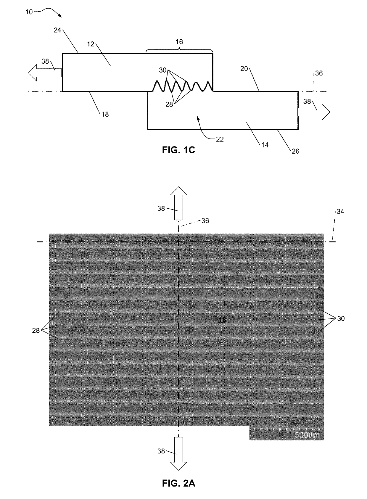
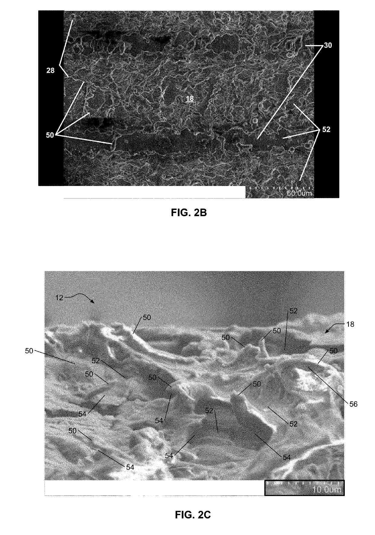
The present patent provides a metal-polymeric composite joint that includes a first component and a second component. The first component has a first surface with micro-anchors, and the second component includes a composite material with a polymer and reinforcing fiber. The second component also has a second surface that at least partially engages the first surface of the first component. The metal-polymeric composite joint has a lap shear strength of greater than or equal to about 6 kN after 5 years. The patent also provides a method of joining dissimilar materials by directing a laser beam or a heat source towards the first surface of the first component to form a plurality of micro-anchors or elongate valleys. The metal-polymeric composite joint has improved mechanical properties and can withstand higher loads.

Problems solved by technology

While use of such lightweight materials can serve to reduce overall weight and generally improve fuel efficiency, issues can arise in manufacturing certain components.
For example, molding large, complex parts from a reinforced composite material may be difficult or infeasible.
However, joining dissimilar materials, such as a metal and a reinforced polymeric composite, may present additional challenges such as low-strength joints or long cycle times in manufacturing.

Method used


Image

  • Laser-induced micro-anchor structural and passivation layer for metal-polymeric composite joining and methods for manufacturing thereof
  • Laser-induced micro-anchor structural and passivation layer for metal-polymeric composite joining and methods for manufacturing thereof
  • Laser-induced micro-anchor structural and passivation layer for metal-polymeric composite joining and methods for manufacturing thereof

Examples


example 1

on Layer

[0083]Referring now to FIG. 10, a first sample includes an aluminum component without a laser-treated surface. A second sample includes an aluminum component that has a laser-treated surface. X-ray photoelectron spectroscopy (XPS) is performed on the first and second samples to obtain depth profiles. An x-axis 180 represents depth measured in nanometers (nm) from a first surface (similar to the first surface 18) toward a third surface (similar to the third surface 24). A y-axis 182 represents an atomic percent of various components.

[0084]A first XPS depth profile 184 represents aluminum content in the first sample. A second XPS depth profile 186 represents oxygen content in the first sample. A third XPS depth profile 188 represents aluminum content in the second sample. A fourth XPS depth profile 190 represents oxygen content in the second sample. The atomic percentages shown for the first and second samples may not add up to 100% because XPS depth profiles of other componen...

example 2

ap Shear Strength and Degradation of Lap Shear Strength Over Time

[0086]With reference to FIGS. 11-14, a first sample includes a metal-polymeric composite assembly having an aluminum component without a laser-treated surface. A second sample 200 includes a metal-polymeric composite assembly having an aluminum component that has a laser-treated surface. A third sample includes a metal-polymeric composite assembly having a stainless steel (316 stainless steel) component that has a laser-treated surface. Each of the first, second, and third samples includes a carbon-fiber reinforced nylon (nylon 6) composite having greater than or equal to about 20% and less than or equal to about 40% carbon fiber by weight.

[0087]Lap shear testing is performed to determine the lap shear strength of each of the samples. Similar samples are aged to test for corrosion. Referring to FIG. 13, an x-axis 210 represents age in years. A y-axis 212 represents lap shear strength in kN. A first curve 214 correspond...


PUM

PropertyMeasurementUnit
spot sizeaaaaaaaaaa
scan speedaaaaaaaaaa
poweraaaaaaaaaa

Abstract

The present disclosure provides a metal-polymeric composite joint including a first component and a second component. The first component includes a metal. The first component has a first surface including a plurality of micro-anchors. The second component includes a composite material including a polymer and a reinforcing fiber. The second component has a second surface that at least partially engages the first surface of the first component. A portion of the polymer of the second component occupies at least a portion of the micro-anchors of the first component to fix the second component to the first component. In one aspect, the metal-polymeric composite joint further includes a passivation layer disposed between the first surface of the first component and the second surface of the second component.

Description

INTRODUCTION[0001]This section provides background information related to the present disclosure which is not necessarily prior art.[0002]The present disclosure pertains to a metal-polymeric composite joint and methods of manufacturing the metal-polymeric composite joint. More specifically, the metal-polymeric composite joint may include a laser-induced micro-anchor structural and passivation layer.[0003]Weight reduction for increased fuel economy in vehicles has spurred the use of various lightweight materials, such as aluminum and magnesium alloys as well as use of light-weight reinforced composite materials. While use of such lightweight materials can serve to reduce overall weight and generally improve fuel efficiency, issues can arise in manufacturing certain components. For example, molding large, complex parts from a reinforced composite material may be difficult or infeasible. It may therefore be desirable to join multiple smaller components. However, joining dissimilar mate...

Claims


Application Information

Patent Timeline
Patent Type & Authority Applications(United States)
IPC IPC(8): B29C65/00B32B3/06B32B3/30B32B15/088B32B27/06B32B27/34B32B37/06B29C65/02
CPCB29C66/303B32B3/06B32B3/30B32B15/088B32B27/06B32B27/34B32B37/06B29C65/02B29C66/7212B29C66/7422B32B2255/06B32B2262/106B32B2307/202B32B2307/542B32B2311/24B32B2377/00B29K2077/00B29K2105/20B29K2705/02B29L2031/30B29C66/30322B29C66/30325B29C66/74283B29C66/71B29L2031/3002B29C66/43B29C66/1122B29C65/8215B29C66/0246B29C66/7392B29C65/8253B29C66/721B29C66/45B29C66/83221B29C65/44B29C65/1629B29C66/73115B32B2255/20B32B27/365B32B15/085B32B15/082B32B27/20B32B27/32B32B2307/538B32B15/18B32B15/09B32B27/38B32B15/092B32B27/302B32B2250/02B32B2274/00B29K2307/04B29K2023/065B29K2069/00B29K2059/00B29K2021/003B29K2055/02B29K2309/08
Inventor WANG, HONGLIANGXIAO, XINGCHENGXIAO, GUOXIANARINEZ, JORGE F.FAN, HUA-TZU
Owner GM GLOBAL TECH OPERATIONS LLC
Features
  • Generate Ideas
  • Intellectual Property
  • Life Sciences
  • Materials
  • Tech Scout
  • Unparalleled Data Quality
  • Higher Quality Content
  • 60% Fewer Hallucinations
Learn More