
Fuel tank

a fuel tank and closed-type technology, applied in the field of closed-type fuel tanks, can solve the problems of increasing the number of component parts and complicated structure, and achieve the effects of easy determination, simplified structure and increased fuel quantity

Active Publication Date: 2019-06-27
KAWASAKI MOTORS LTD
View PDF11 Cites 1 Cited by
  • Summary
  • Abstract
  • Description
  • Claims
  • Application Information

AI Technical Summary

Benefits of technology

This patent describes a construction for a fuel tank system that prevents fuel from splashing during fueling. The system includes an oil feed tube with a vent hole that allows air to escape from the tank, while also allowing more fuel to accumulate. An index indicative of the fuel level is provided to easily determine how much fuel is in the tank. The oil feed tube is inclined to facilitate fuel flow and the vent hole includes a seal and a positioner to control its opening and closing. The total surface area of the vent holes is larger than the space between the open end and the seal, ensuring smooth discharge of gas from the tank. This design simplifies the construction and allows for increased fuel accumulation, while also facilitating fueling and controlling fuel level.

Problems solved by technology

If the oil feed port is opened under this condition during the fuel filling, it may occur that the fluid level within the tank main body is pressurized by the internal pressure to such an extent as to result in squirt of the liquid fuel from the oil feed port.
For this reason, the number of component parts increases and the structure is also complicated.

Method used


Image

  • Fuel tank
  • Fuel tank
  • Fuel tank

Examples


Embodiment Construction

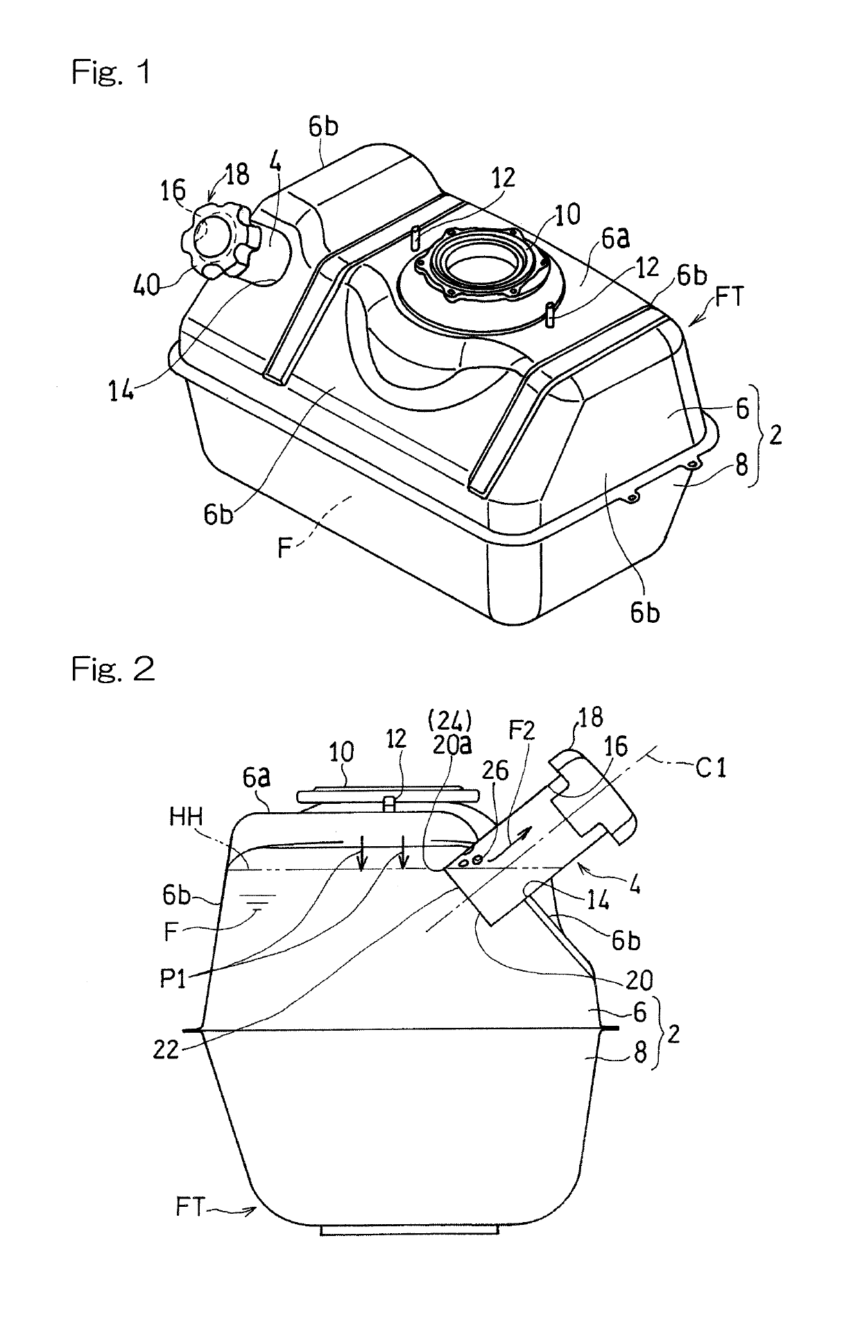
[0022]Hereinafter, the preset invention will be described in connection with preferred embodiments thereof with reference to the accompanying drawings. In particular, FIG. 1 illustrates a diagram showing a fuel tank FT according to a first preferred embodiment of the present invention. The fuel tank FT according to this embodiment is applied to, for example, a utility vehicle. The utility vehicle referred to above includes a vehicle such as all-terrain vehicle generally known as a four-wheeled buggy and means a vehicle capable of being driven on any geographical surface such as, for example, a muddy land, sand beach and / or snowy road. The utility vehicle is used in a variety of applications including, for example, leisure and / or or work. It is, however, to be noted that the fuel tank of the present invention can also be applied to any other vehicle than the utility vehicle and can also be applied to any engine other than the vehicle.

[0023]The fuel tank FT includes a tank main body 2...


PUM


Abstract

A fuel tank includes a tank main body configured to reserve a quantity of fuel therein and an oil feed tube fitted to the tank main body to form a fuel feed port. The fuel feed tube has a tip end configured to protrude inwardly of the tank main body, and the tip end is positioned below the upper limit level of the fuel. At a location of the fuel feed tube above the upper limit level, a vent hole is formed to communicate between the interior of the tank main body and the interior of the oil feed tube.

Description

CROSS REFERENCE TO THE RELATED APPLICATION[0001]This application is based on and claims Convention priority to Japanese patent application No. 2017-244617, filed Dec. 21, 2017, the entire disclosure of which is herein incorporated by reference as a part of this application.BACKGROUND OF THE INVENTIONField of the Invention[0002]The present invention relates to a closed type fuel tank including a tank main body to reserve a quantity of fuel therein and an oil feed tube fitted to the tank main body to define an oil feed port.Description of Related Art[0003]Fuel tanks generally mounted on vehicles such as, for example, automotive vehicles are of a structure in which fuel can be supplied into a tank main body through an oil feed tube and an oil feed port thereof is then closed. For example, it may occur that the fuel within the interior is vaporized as a result of change in temperature, accompanied by increase of the internal pressure inside the tank main body. If the oil feed port is op...

Claims


Application Information

Patent Timeline
Patent Type & Authority Applications(United States)
IPC IPC(8): B60K15/035
CPCB60K15/035B60K2015/03552B60K2015/03576B60K15/04B60K2015/0438B60K2015/0451B60K2015/0496
Inventor YAMAMOTO, TERUAKI
Owner KAWASAKI MOTORS LTD
Features
  • Generate Ideas
  • Intellectual Property
  • Life Sciences
  • Materials
  • Tech Scout
  • Unparalleled Data Quality
  • Higher Quality Content
  • 60% Fewer Hallucinations
Learn More