Control device for internal combustion engine

a control device and internal combustion engine technology, applied in the direction of electric control, fuel injection apparatus, charge feed system, etc., can solve the problem of higher achieve low viscosity, increase the discharge amount of the high-pressure fuel pump, and reduce the effect of fuel pressure in the accumulator

Active Publication Date: 2019-06-27
DENSO CORP
View PDF0 Cites 2 Cited by
  • Summary
  • Abstract
  • Description
  • Claims
  • Application Information

AI Technical Summary

Benefits of technology

[0011]An idle speed of the internal combustion engine is increased to a specified speed when the fuel pressure in the accumulator has been higher than a determination pressure, which is lower than the specified pressure, for a first period or longer. The high-pressure fuel pump is driven by the driving shaft of the internal combustion engine. By increasing the idle speed of the internal combustion engine, the discharge amount of the high-pressure fuel pump can be increased. Thus, even if the high-pressure fuel pump is deteriorated or the low viscosity fuel is used, the fuel pressure in the accumulator can be easily increased to the valve opening pressure of the relief valve. As a result, when the high-pressure fuel pump has a malfunction, the fuel pressure in the accumulator can be easily decreased, so that the design withstand pressure of the accumulator can be lowered.

Problems solved by technology

However, if the high-pressure fuel pump is deteriorated or a low-viscosity fuel is used, the fuel pressure in the accumulator becomes higher than the normal range and becomes lower than the valve opening pressure of the relief valve when the high-pressure fuel pump has a malfunction.

Method used


Image

  • Control device for internal combustion engine
  • Control device for internal combustion engine
  • Control device for internal combustion engine

Examples


Embodiment Construction

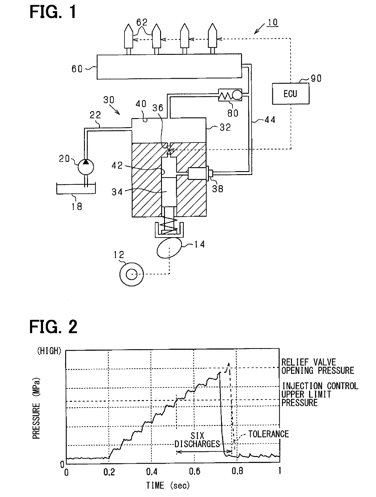
[0021]Referring to drawings, an embodiment which is applied to a four-cylinder gasoline engine (internal combustion engine) will be described.

[0022]As shown in FIG. 1, an engine 10 is provided with a crankshaft 12 (a drive shaft), a cam 14, a low-pressure fuel pump 20, a high-pressure fuel pump 30, a delivery pipe 60, a fuel injector 62, a relief valve 80, etc. The cam 14 is driven by the crankshaft 12.

[0023]The low-pressure fuel pump 20 suctions fuel in a fuel tank 18, pressurizes the fuel, and discharges the pressurized fuel. The pressure of fuel discharged by the low-pressure fuel pump 20 is regulated by a regulator (not shown).

[0024]The high-pressure fuel pump 30 includes a cylinder body 32, a plunger 34, a metering valve 36, a discharge valve 38, and the like.

[0025]The cylinder body 32 defines a low pressure chamber 40 and a pressurizing chamber 42. The fuel discharged by the low-pressure fuel pump 20 is supplied to the low-pressure chamber 40 (corresponding to a specified cham...


PUM


Abstract

A control device is applied for an internal combustion engine which is provided with a high-pressure fuel pump driven by a driving shaft of the internal combustion engine to discharge a fuel pressurized in a pressurizing chamber, an accumulator accumulating a high-pressure fuel discharged from the high-pressure fuel pump, and a relief valve which is opened when a fuel pressure in the accumulator is higher than a specified pressure in order to return the fuel in the accumulator to a specified chamber where a fuel has lower pressure than a fuel in the pressurizing chamber. An idle speed of the internal combustion engine is increased to a specified speed when the fuel pressure in the accumulator has been higher than a determination pressure, which is lower than the specified pressure, for a first period or longer.

Description

CROSS REFERENCE TO RELATED APPLICATION[0001]This application is based on Japanese Patent Application No. 2016-063161 filed on Mar. 28, 2016, the disclosure of which is incorporated herein by reference.TECHNICAL FIELD[0002]The present disclosure relates to a control device for an internal combustion engine provided with a high-pressure fuel pump.BACKGROUND ART[0003]Conventionally, when a high-pressure fuel pump has a malfunction, a relief valve is opened so that a maximum pressure in an accumulator does not exceed a valve-opening limit pressure of a fuel injector.PRIOR ART LITERATUREPatent Literature[0004]Patent Literature 1: Japanese Patent No. 5525760SUMMARY OF INVENTION[0005]In a device shown in Patent Literature 1, when the relief valve is opened, the fuel pressure in the accumulator is lower than the valve-opening limit pressure of the fuel injector, but is higher than a normal range. If the accumulator is continuously used at a pressure higher than the normal range, it is likel...

Claims


Application Information

Patent Timeline
Patent Type & Authority Applications(United States)
IPC IPC(8): F02D45/00F02M55/02
CPCF02D45/00F02M55/02F02M63/0225F02M2200/80F02D41/3845F02D41/3863F02D2200/0602F02D41/08F02M63/025F02D41/3836F02D41/3854F02D41/042F02D2250/31F02M63/0245F02M63/0235F02D31/003
Inventor HIRATA, YASUO
Owner DENSO CORP
Why Eureka
Try Eureka