Flow generator

Inactive Publication Date: 2020-06-18
LG ELECTRONICS INC
View PDF0 Cites 0 Cited by
  • Summary
  • Abstract
  • Description
  • Claims
  • Application Information

AI Technical Summary

Benefits of technology

The present invention improves the air flow and blowing capacity of an electrical fan device by using a main body with an upper and lower module that rotate to increase air discharge. The flow generator is easily assembled or disassembled for improved controllability and safety. The air is easily discharged in the radial direction by an air guide device, and the upper and lower modules rotate to discharge air in various directions. These technical effects improve the performance and user experience of the electrical fan device.

Problems solved by technology

In the device according to the prior art document 1, although a safety cover surrounding the outside of the fan is provided for a reason of safety, there is still a concern that a users finger passes through the safety cover to touch the fan.
Also, if a large amount of dust exists in a space in which the device is placed, there is a problem that the dust is easily accumulated in the fan through the safety cover, and thus, the device becomes easily dirty.
Also, in the devices according to the prior art documents 1 and 2, in terms of simply generating an air flow to be supplied to the user, if the device is used in a space with a high degree of contamination, the users health may be deteriorated.
As a result, there is a problem that the usability of the device is deteriorated.

Method used


Image

  • Flow generator
  • Flow generator
  • Flow generator

Examples


first embodiment

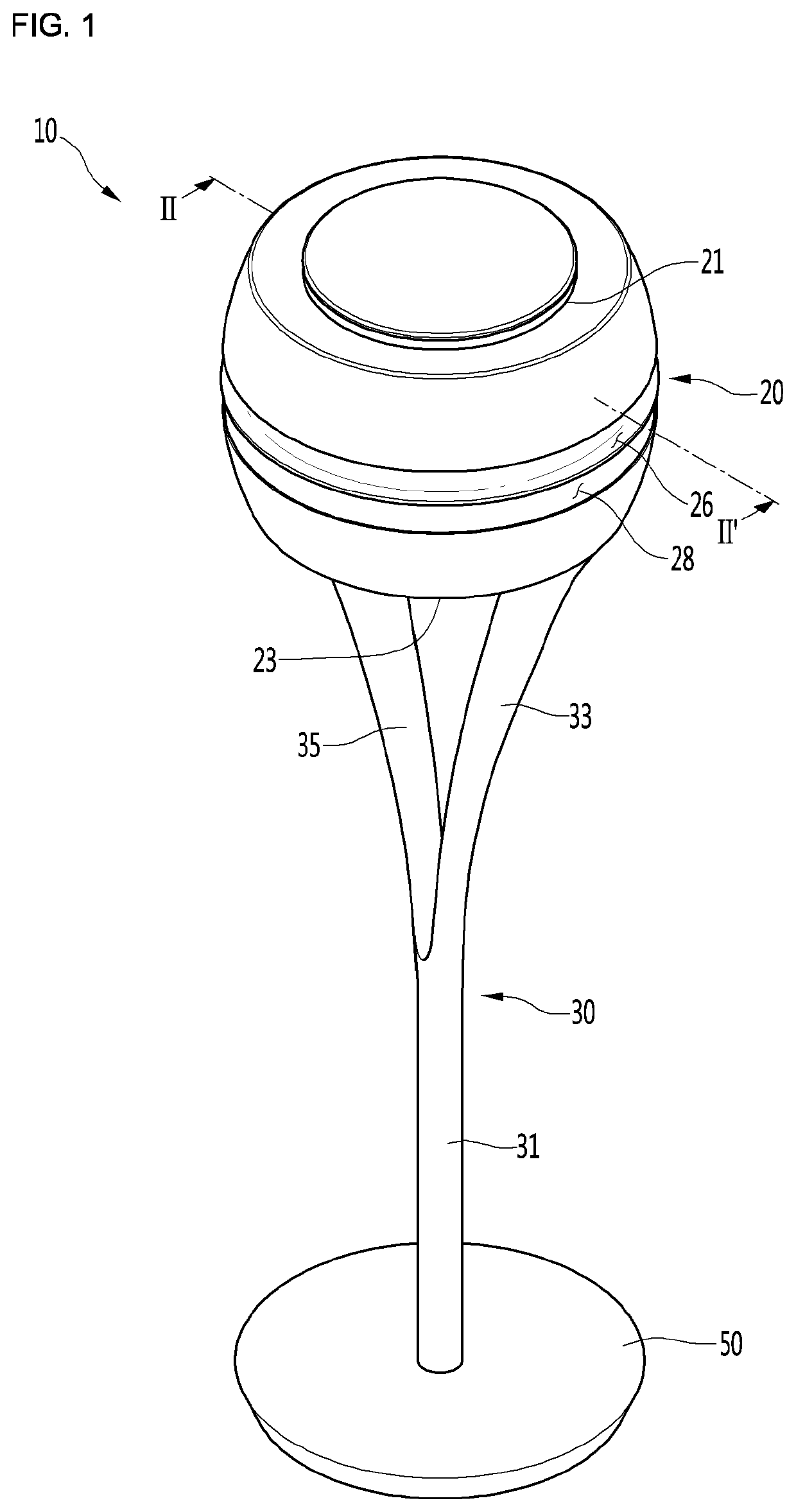
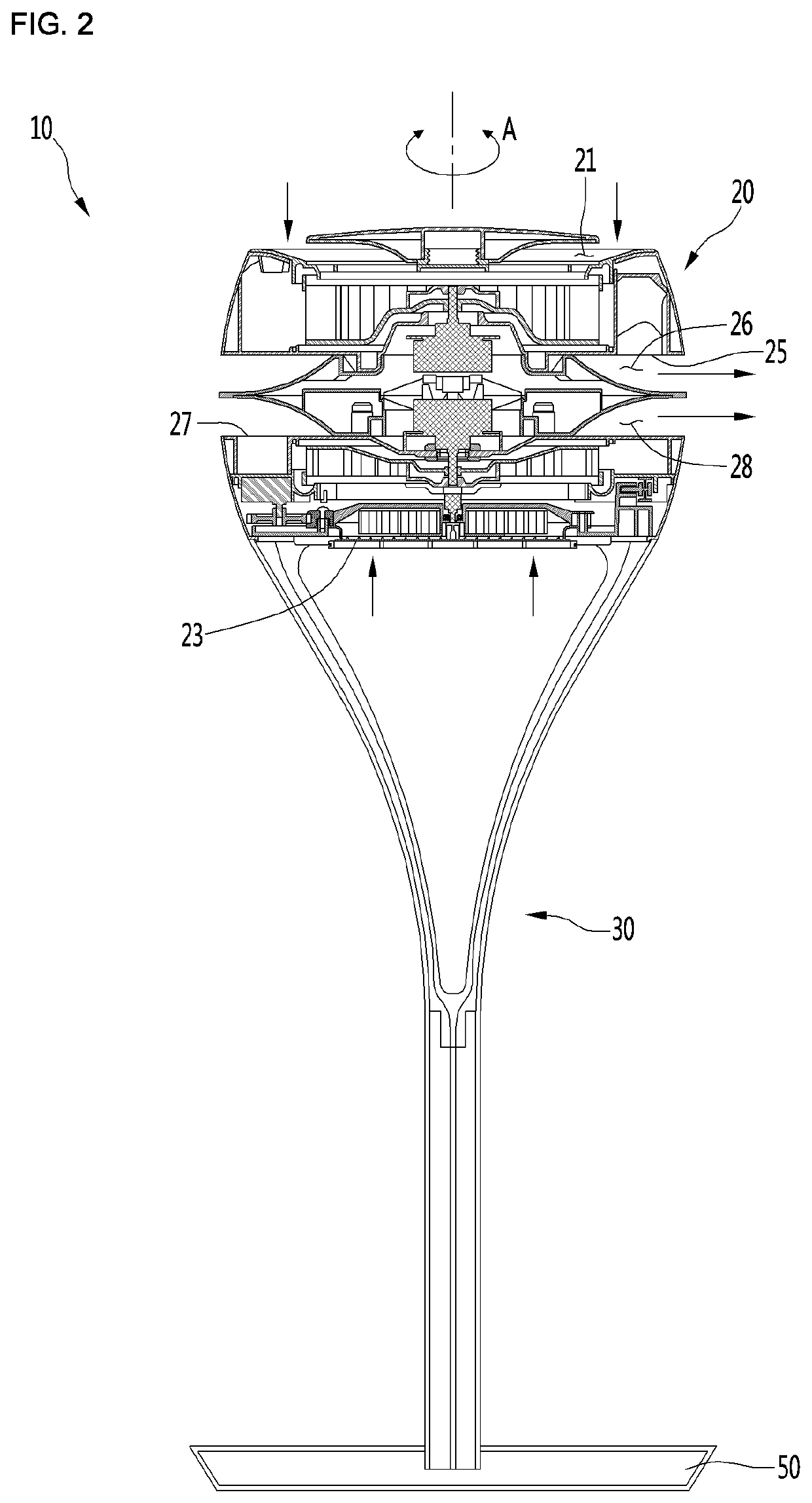
[0068]FIG. 1 is a perspective view illustrating a configuration of a flow generator according to a first embodiment of the present invention, and FIG. 2 is a cross-sectional view taken along line II-II′ of FIG. 1.

[0069][Main Body]

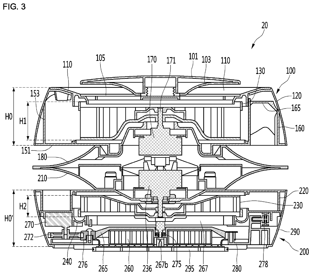
[0070]Referring to FIGS. 1 and 2, a flow generator 10 according to an embodiment of the present invention includes a main body 20 including suction parts 21 and 23 through which air is suctioned and discharge parts 25 and 27 through which air is discharged.

[0071][First and Second Suction Parts]

[0072]The suction parts 21 and 23 include a first suction part 21 provided in an upper portion of the main body 20 and a second suction part 23 provided in a lower portion of the main body 20. Air suctioned through the first suction part 21 may flow downward to be discharged to a central portion of the main body 21. Also, air suctioned through the second suction part 23 may flow upward to be discharged to a central portion of the main body 21. The “central portion” of...


PUM


Abstract

A flow generator according to an embodiment of the present invention includes: a fan configured to generate a first air flow and a second air flow, which flow to close to each other in a vertical direction; a fan housing configured to accommodate the fan; a cover disposed to surround the fan and the fan housing; and a catch device configured to guide selective coupling between the cover and the fan housing, wherein the catch device perform a first operation to restrict or release the cover and the fan housing in a circumferential direction and perform a second operation to restrict or release the cover and the fan housing in the vertical direction.

Description

TECHNICAL FIELD[0001]Embodiments of the present invention relate to a flow generator.BACKGROUND ART[0002]Generally, a flow generator is understood as a device for driving a fan to generate an air flow and blowing the generated air flow to a position desired by a user. The flow generator is usually called a “fan”. Such a flow generator may be mainly disposed in an indoor space such as a home or office and be used to provide cool and pleasant feeling to a user in hot weather such as summer.[0003]With respect to this flow generator, techniques of the following prior art document has been proposed in the related art.PRIOR ART DOCUMENT 1[0004]1. Publication Number (Publication Date): 10-2012-0049182 (May 16, 2012)[0005]2. Title of The Invention: Axial FanPRIOR ART DOCUMENT 2[0006]1. Publication Number (Publication Date): 10-2008-0087365 (Oct. 1, 2008)[0007]2. Title of The Invention: Electric Fan[0008]Each of the devices according to the prior art documents 1 and 2 includes a support plac...

Claims


Application Information

Patent Timeline
IPC IPC(8): F04D25/08F04D25/16
CPCF04D25/166F04D29/4226F04D25/08F04D29/462F04D29/441F04D17/16F04D29/424F04D29/624F04D25/0693F05D2270/52F24F2221/38F24F8/10F24F11/0001
Inventor PARK, HEECHULKU, MYUNGJINBAE, JUNSEOK
Owner LG ELECTRONICS INC
Why Eureka
Try Eureka