Terminal fitting

a technology of fittings and fittings, applied in the direction of coupling devices, coupling devices effected by permanent deformation, coupling devices, etc., can solve the problems of shield crimping pieces opening, shield conductor connection reliability cannot be guaranteed, etc., to suppress the opening of shield crimping pieces, prevent deformation and fracture of shield layers, and reduce the effect of crimping pieces

Active Publication Date: 2019-06-27
SUMITOMO WIRING SYST LTD
View PDF7 Cites 9 Cited by
  • Summary
  • Abstract
  • Description
  • Claims
  • Application Information

AI Technical Summary

Benefits of technology

[0006]The two shield crimping pieces can be crimped to the shield layer at a low compression ratio to prevent deformation and fracture of the shield layer. Thus, a shield layer in the form of a braided wire will not distort and an opening diameter can be made substantially uniform. There generally is a concern that the shield crimping pieces may open if the compression ratio is low. However, the surrounding portion of the subject invention surrounds the outer peripheries of the shield crimping pieces to suppress opening of the shield crimping pieces. As a result, the shield crimping pieces remain crimped to the shield layer and a satisfactory shielding function can be exhibited.
[0007]The two shield crimping pieces may rise from a body of the outer conductor. The surrounding portion may include two strips rising from a body of the cover and may be deformable along the outer peripheries of the shield crimping pieces. The body of the cover may cover tips of the shield crimping pieces to reliably suppress the opening of the shield crimping pieces.
[0008]The body of the outer conductor may include a ...

Problems solved by technology

However, the reduced compression ratio may permit projecting pieces of the shield crimping portion to expand so that connection reliability...

Method used


Image

  • Terminal fitting
  • Terminal fitting
  • Terminal fitting

Examples


Embodiment Construction

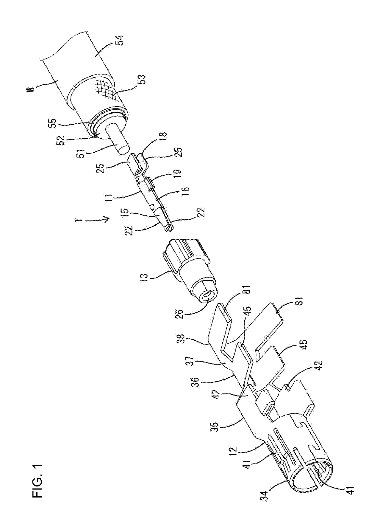
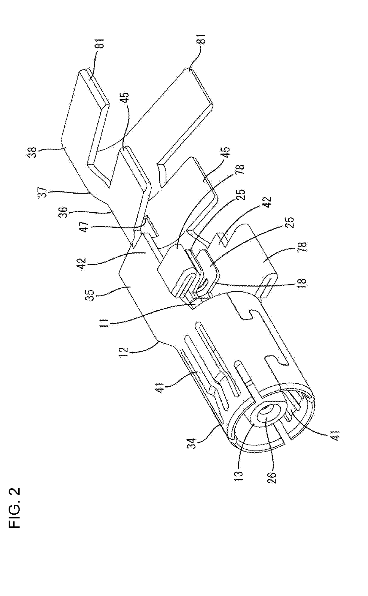
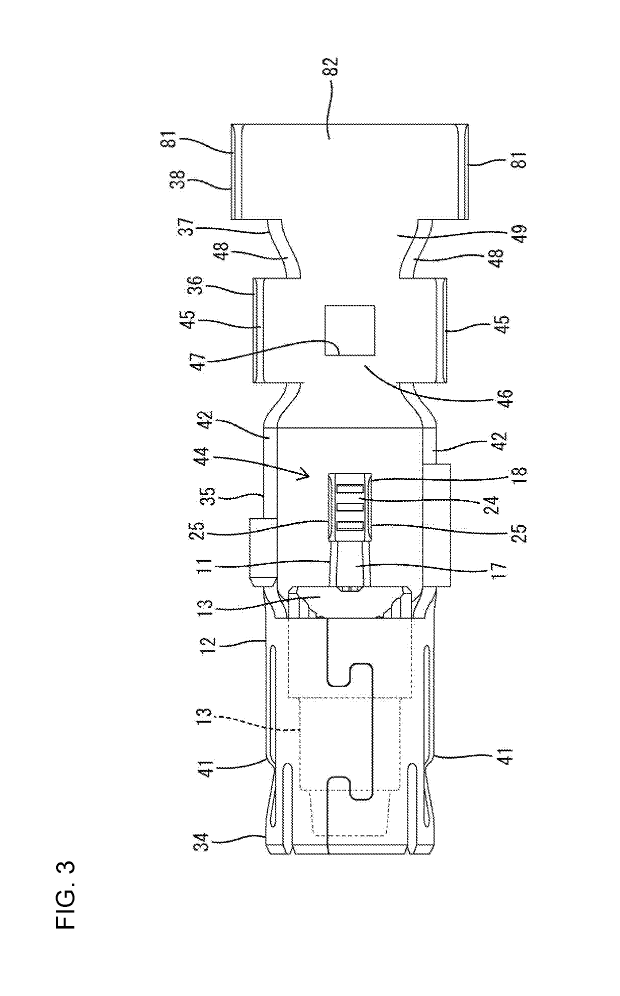
[0030]An embodiment is described with reference to the drawings. A terminal fitting T according to this embodiment is connected to an end part of a shielded cable W and includes, as shown in FIG. 1, an inner conductor 11, an outer conductor 12, a dielectric 13 and a cover 14. The inner conductor 11, the outer conductor 12 and the cover 14 are made of a conductive metal, and the dielectric 13 is made of an insulating synthetic resin. This terminal fitting T is connected electrically to a mating terminal fitting 60 from the front.

[0031]As shown in FIG. 1, the shielded cable W is a so-called coaxial cable and includes a conductive core 51 (center conductor) formed by twisting a plurality of strands, an insulating coating 52 surrounding the outer periphery of the core 51, a conductive braided wire 53 (shield layer) formed by weaving strands into a net that surrounds the outer periphery of the coating 52 and an insulating sheath 54 surrounding the outer periphery of the braided wire 53. ...


PUM


Abstract

A terminal fitting (T) includes an inner conductor (11), an outer conductor (12) and a dielectric (13) interposed between these conductors. The inner conductor (11) is connected to a core (51) of a shielded cable (W). The outer conductor (12) includes two shield crimping pieces (45) deformable along an outer periphery of a braided wire (53) of the shielded cable (W). Further, the terminal fitting (T) includes a cover (14) including a shield-side surrounding portion (84) for surrounding the shield crimping pieces (45) along outer peripheries thereof.

Description

BACKGROUNDField of the Invention[0001]The invention relates to a terminal fitting.Related Art[0002]A high-frequency compatible shielded cable often is routed in an automotive vehicle to transmit a high-frequency signal to a circuit board of an electrical device, such as a television or car navigation system mounted in the vehicle. For example, Japanese Unexamined Patent Publication No. 2015-162375 discloses a coaxial cable (shielded cable) with a coaxial connector (terminal fitting) mounted on an end part for connection to an electrical device. The coaxial cable includes an inner conductor terminal, an outer conductor terminal and a dielectric interposed between the inner and outer conductor terminals. The inner conductor terminal is connected to a core of the coaxial cable. The outer conductor terminal includes a hollow cylindrical portion for accommodating the dielectric and the inner conductor terminal on a front part and a shield crimping portion to be crimped to a shield conduc...

Claims


Application Information

Patent Timeline
IPC IPC(8): H01R9/05H01R4/18H01R13/6592H01R13/6581
CPCH01R9/0518H01R4/185H01R13/6592H01R13/6581H01R24/568H01R24/40H01R24/44H01R4/184H01R2103/00
Inventor KANEMURA, KEISUKENAKANISHI, YUICHIHIRANO, AIMITSUI, SHOHEI
Owner SUMITOMO WIRING SYST LTD
Why Eureka
Try Eureka