System for controlling electrical power generation

Inactive Publication Date: 2019-06-27
DENDYUK VLADIMIR ANTONOVICH
View PDF7 Cites 0 Cited by
  • Summary
  • Abstract
  • Description
  • Claims
  • Application Information

AI Technical Summary

Benefits of technology

The invention aims to improve the reliability of power generation control systems in emergency situations and address the shortcomings of existing systems. The technical effects include better control and reliability of power generation equipment, as well as improved operational efficiency and reliability in emergency situations.

Problems solved by technology

A major drawback of similar known systems is an insufficient reliability in conditions of emergency switching off the power generating equipment (blackouts), and in conditions of abrupt and unexpected weather changes, as well as impossibility of manual control in such conditions.

Method used


Image

  • System for controlling electrical power generation

Examples


Embodiment Construction

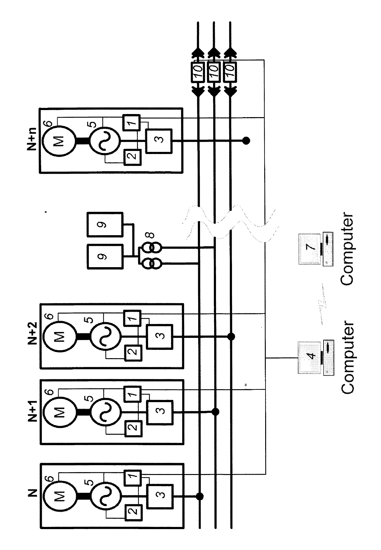
[0014]The proposed system for control of electrical power generation is illustrated on FIGURE. The base portion of the system is a plurality of power generating units N, N+1, N+2, . . . , N+n, which provide for generation of electric energy, and which are parallel connected to an electric grid. FIGURE depicts the embodiment that employs power generating units utilizing the aforesaid mobile automatic electric stations.

[0015]Active load devices 9 are associated with the electric grid via transformers 8 connected in parallel to the power generating units N, N+1, N+2, . . . , N+n. Each of the power generating units includes known equipment: a primary power installation 6 (a gas-turbine or diesel engine, or an engine of another conventional type), an electric generator 5, circuit breakers 3 and 10, thermostated programmable means of control and circuit protection 1 and 2.

[0016]The programmable means of control and circuit protection 1, 2 include controllers 1 and an excitation circuitry ...


PUM


Abstract

The proposed system for controlling electrical power generation includes power generating units each having an electrical generator parallel-connected to an electric grid via a circuit breaker, programmable control and protection means, and a primary power engine. At least one active loading device is connected to the grid parallel to the generator. The programmable control and protection means include a microprocessor-based excitation system, an automatic excitation regulation controller, and an electrical generator differential protection controller. The controllers are connected to one another and to the microprocessor-based excitation system, the circuit breaker and a plant computer for controlling the power generating units, the plant computer being the end point in a two-way wireless communication link with a dispatch computer for remotely controlling and monitoring the power generating units.

Description

CROSS-REFERENCES TO RELATED APPLICATIONS[0001]This application is a U.S. national stage application of a PCT application PCT / RU2011 / 000737 filed on 27 Sep. 2011, published as WO / 2012 / 053934, whose disclosure is incorporated herein in its entirety by reference, which PCT application claims priority of a Russian Federation application RU2010143233 filed on 22 Oct. 2010, now a Russian Federation Patent RU2435270 issued on 27 Nov. 2011.FIELD OF INVENTION[0002]The proposed invention relates to the field of generation of electrical power and can be utilized for control of generation of electrical energy, preferably, in extreme climate conditions.BACKGROUND OF THE INVENTION[0003]As a related art system nearest to the proposed invention, the instant inventors consider a system for control of electrical energy generation taught in U.S. Pat. No. 5,973,481 issued 26 Oct. 1999 to National Bank of Alaska, Alaska Science and Technology Foundation. The system described in U.S. Pat. No. 5,973,481 i...

Claims


Application Information

Patent Timeline
IPC IPC(8): H02J3/38H02J13/00H02H7/06H02H1/00G05B15/02
CPCH02J3/381H02J13/0075H02H7/06H02H1/0061H02H1/0092G05B15/02H02H7/261H02J2300/10H02J13/00016H02J13/0004Y04S10/12Y04S10/20Y04S40/124Y04S40/126Y02E40/70Y02B90/20Y02E60/00H02J7/007194
Inventor DENDYUK, VLADIMIR ANTONOVICH
Owner DENDYUK VLADIMIR ANTONOVICH
Why Eureka
Try Eureka