Exhaust system having tunable exhaust sound
Active Publication Date: 2019-07-04
FORD GLOBAL TECH LLC
8 Cites 1 Cited by
AI-Extracted Technical Summary
Problems solved by technology
The cost of the vehicle may be increased when multiple resonators are utilized as opposed to a single resonator.
An additional undesirable result to this approach is the size increase of the exhaust system when multiple...
Benefits of technology
[0009]At least one of the conduits has peripheral perforations formed on it in the second expansion chamber and the other of the conduits has peripheral perforatio...
Abstract
The disclosed inventive concept provides a further achievement in efforts to produce a tunable exhaust sound for a vehicle. The system provides a tunable exhaust system including a tunable resonator and a pair of tunable mufflers. The tunable resonator includes a housing including first, second and third expansion chambers. A pair of bank-by-bank exhaust conduits extends through the housing. At least one of the conduits includes a band of peripheral perforations within the first expansion chamber. The band is formed at an angle relative to the long axis of the conduit on which it is formed. The mufflers include inlet and outlet pipes. At least one of the outlet pipes includes a variable exhaust gas flow assembly. The variable exhaust gas flow assembly includes a vane shaft, an exhaust gas regulating vane attached to the vane shaft, and a vane actuator for regulating the position of the vane shaft.
Application Domain
Silencing apparatusMachines/engines +2
Technology Topic
Exhaust gasResonator +6
Image
Examples
- Experimental program(1)
Example
[0029]In the following figures, the same reference numerals will be used to refer to the same components. In the following description, various operating parameters and components are described for different constructed embodiments. These specific parameters and components are included as examples and are not meant to be limiting.
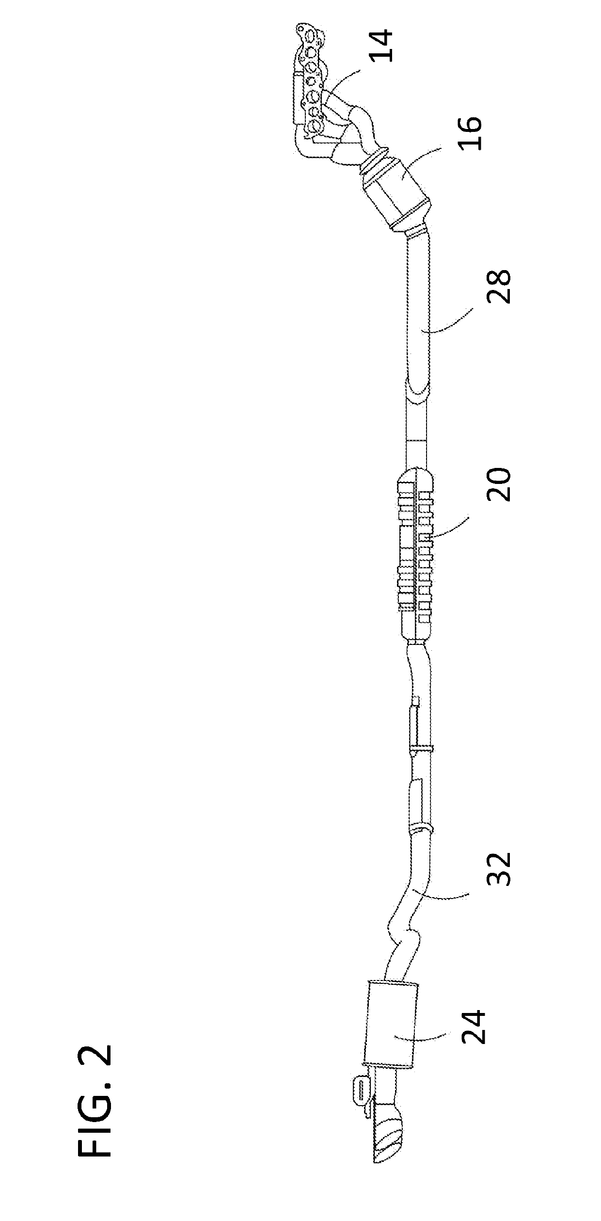
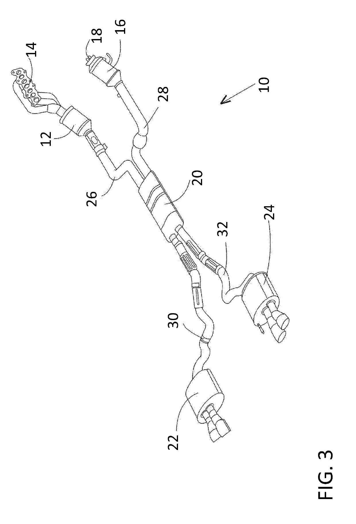
[0030]The accompanying figures show various related interpretations of the disclosed inventive concept which provides an exhaust system having a tunable exhaust sound which incorporates a resonator, a pair of mufflers, and pipes to connect the resonator to the catalytic converters and the resonator to the mufflers. The exhaust system of the disclosed inventive concept is intended for use with engines having a V-configuration but may be adapted for use with other types of engines. In addition, while the exhaust system of the disclosed inventive concept illustrates described versions of resonators being used with described versions of mufflers with some mufflers having a variable exhaust gas flow assembly, the resonators and mufflers described herein can be used separately and not in combination in certain applications.
[0031]In general, the exhaust system having a tunable exhaust sound is illustrated in FIGS. 1 through 3, embodiments of a resonator for use in such a system are illustrated in FIGS. 4 through 7, and embodiments of mufflers for use in such a system are illustrated in FIGS. 8 through 14. It is to be understood that the concepts illustrated in the accompanying figures and discussed in relation thereto are not intended as being limiting as certain variations, such as the sizes and lengths of the exhaust conduits, the placement of the baffles, and the lengths, widths and depths of the resonators and mufflers may be varied without deviating from the disclosed inventive concept as discussed hereafter.
[0032]The disclosed inventive concept solves the limitations of known exhaust systems by providing staggered perforations in two independent chambers of a close coupled resonator, and a tuned amount of mixing via perforations in a separate forward chamber. The exhaust system controls ½-engine order sound by tuning the relative lengths of pipe in each bank and by controlling the amount of mixing between the two banks. The staggered perforations create asymmetry between the two banks of the exhaust system, enhancing all the half order sounds, while the controlled mixing in the first chamber aids with exhaust gas scavenging to aid engine power. The perforations in the first chamber can be used to further fine tune the exhaust order content by changing the number of holes, size of the holes, and locations of the holes in the perforations. This approach also helps eliminate the flutter noise error state created from a system with no mixing between banks. The amount and spacing of the perforations between the rear 2 chambers can also be used to further tune half order sound, and minimize exhaust rasp error states, so high frequency rasp does not become the dominating exhaust character. Accordingly, the exhaust system having a tunable exhaust sound as disclosed herein provides an added level of tuning control that never previously existed. This control enables fine tuning of desired acoustic order content while minimizing error states.
[0033]Referring to FIGS. 1 through 3, various views of the exhaust system having a tunable exhaust sound according to the disclosed inventive concept are illustrated. The exhaust system having tunable exhaust sound, generally illustrated as 10, includes a left bank catalytic converter 12, a left bank exhaust header 14, a right bank catalytic converter 16, and a right bank catalytic converter attachment flange 18. The left bank catalytic converter 12 is attached to the left bank exhaust header 14 by an attachment flange that is not illustrated.
[0034]The exhaust system having a tunable exhaust sound 10 further includes a tunable resonator 20, a tunable left bank dual mode muffler 22, and a tunable right bank dual mode muffler 24. The resonator 20 is attached to the left bank catalytic converter 12 by a left bank header-to-resonator pipe 26 and the resonator 20 is attached to the right bank catalytic converter 16 by a right bank header-to-resonator pipe 28. The resonator 20 is attached to the left bank dual mode muffler 22 by a left bank resonator-to-muffler pipe 30 and the resonator 20 is attached to the right bank dual mode muffler 24 by a right bank resonator-to-muffler pipe 32. It is to be understood that the placement and shapes of the various components of the exhaust system having a tunable exhaust sound 10 may be adapted for applications other than that illustrated in the various figures.
[0035]FIGS. 4 and 5 illustrate top sectional and bank sectional views respectively of the resonator 20. The resonator 20 includes a housing 40 defining an enclosure. A portion of the housing has been removed to reveal the inner components. However, it will be understood that the enclosure is substantially sealed from the surrounding environment (i.e., isolated from ambient air). The resonator 20 includes a left bank pipe 42 that is attached to the left bank header-to-resonator pipe 26 (shown, for example, in FIG. 1) at a left bank pipe inlet 44. The left bank pipe 42 is attached to the left bank resonator-to-muffler pipe 30 (also shown, for example, in FIG. 1) at a left bank pipe outlet 46. The resonator 20 further includes a right bank pipe 48 that is attached to the right bank header-to-resonator pipe 28 (shown, for example, in FIG. 1) at a right bank pipe inlet 50. The right bank pipe 48 is attached to the right bank resonator-to-muffler pipe 32 (also shown, for example, in FIG. 1) at a right bank pipe outlet 52. The long axes of the left bank pipe 42 and the right bank pipe 48 are substantially parallel. However in other examples, other conduit orientations are possible. In addition, the diameter of each of the left bank pipe 42 and the right bank pipe 48 extending through the housing 40 are preferably but not absolutely substantially equal.
[0036]The resonator 20 further includes a front wall 54, a first baffle 56, a second baffle 58, and a back wall 60. The resonator housing 40 and the baffles 56 and 58 may be constructed out of a suitable material such as steel, aluminum, or a polymer. Specifically, a multi-layer housing construction may be employed. For example, an insulator may be positioned between two metal layers to provide sound dampening. However in other examples, other constructions may be used such as a single layer metal housing.
[0037]As shown, the front and rear surfaces of the baffles 56 and 58 are substantially flat. However, in other examples, one or more of the surfaces may be curved. A first expansion chamber 62 is formed between the front wall 54 and the first baffle 56. A second expansion chamber 64 is formed between the first baffle 56 and the second baffle 58. A third expansion chamber 66 is formed between the second baffle 58 and the back wall 60. The first expansion chamber 62 is positioned upstream of the second expansion chamber 64 which is positioned upstream of the third expansion chamber 66. However, in other examples, one or both of the baffles may extend lengthwise in the enclosure. Specifically in some examples, one or both of the baffles may be parallel to the central axes first and/or second exhaust conduits. One or both of the baffles may include one or more openings (not shown) to fluidly couple adjacent expansion chambers as desired for sound tuning.
[0038]In the first expansion chamber 62, the left bank pipe 42 includes a left first perforated portion 70 defined by a relatively narrow band of perforations that ring the left bank pipe 42 and the right bank pipe 48 includes a right first perforated portion 72 defined by a relatively narrow band of perforations that ring the right bank pipe 48. As illustrated in FIG. 5, the perforated portion 70 (and the perforated portion 72) is formed at an angle around the pipes relative to the long axis of the pipes. This arrangement also aids the designer in tuning the sound of the system. Both of the perforated portions 70 and 72 are relatively narrow compared with other pipe perforations as illustrated in FIGS. 4 and 5 and as discussed in conjunction therewith.
[0039]In the second expansion chamber 64, the left bank pipe 42 includes a second left perforated portion 74 defined by a relatively wide band of perforations that ring the left bank pipe 42. The right bank pipe 48 is free of perforations in the second expansion chamber 64. In the third expansion chamber 66, the right bank pipe 48 includes a second right perforated portion 76 defined by a relatively wide band of perforations that ring the right bank pipe 48. The left bank pipe 42 is free of perforations in the third expansion chamber 66. It is to be understood that while the left bank pipe 42 includes perforations and the right bank pipe 48 is free of perforations in the second expansion chamber 64 and the right bank pipe 48 includes perforations and the left bank pipe 42 is free of perforations in the third expansion chamber 66, the opposite may be the case.
[0040]The size, number, and spacing of the perforations in both of the exhaust conduits may be identical. However, in other examples one perforated portion may include a varying number of perforations, differently sized perforations, and/or differently spaced perforations from another perforated portion. Furthermore, the perforations in the left bank pipe 42 may be asymmetric and the perforations in the right bank pipe 48 may be symmetric or vice versa. In addition, the perforations in one of the perforated portions may be larger than the perforations in another perforated portion. Still further, the sizes of the perforations in a single perforated portion may differ.
[0041]Moreover, the perforations may extend radially around each portion of the pipes 42 and 48. Particularly, the perforations may extend a full 360° around the portion (around the entire circumference) of the exhaust conduits enclosed in the resonator housing 40. In other embodiments, the perforations may only partially extend radially around the exhaust conduits. In some examples the perforations may extend between 45°-180° around one or both of the pipes 42 and 48. In such an example, the perforations may face the outer wall of the housing 40 or may face the center of the enclosure to direct the sound wave in a direction that is conducive to attenuating the targeted frequency or frequency ranges generated by the engine in the exhaust.
[0042]FIG. 6 illustrates a top sectional view of an alternate embodiment of a resonator for use in the disclosed exhaust system having a tunable exhaust sound. The resonator, generally illustrated as 80, includes a housing 82 defining an enclosure. A portion of the housing has been removed to reveal the inner components. However, it will be understood that the enclosure is substantially sealed from the surrounding environment. The resonator 80 includes a left bank pipe 84 that is attached to the left bank header-to-resonator pipe 26 at a left pipe inlet 86. The left bank pipe 84 is attached to the left bank resonator-to-muffler pipe 30 (also shown, for example, in FIG. 1) at a left bank pipe outlet 88. The resonator 80 further includes a right bank pipe 90 that is attached to the right bank header-to-resonator pipe 28 (shown, for example, in FIG. 1) at a right bank pipe inlet 92. The right bank pipe 90 is attached to the right bank resonator-to-muffler pipe 32 (also shown, for example, in FIG. 1) at a right bank pipe outlet 94. The long axes of the left bank pipe 84 and the right bank pipe 90 are substantially parallel. However in other examples, other conduit orientations are possible. In addition, the diameter of each of the left bank pipe 84 and the right bank pipe 90 extending through the housing 82 are preferably but not absolutely substantially equal.
[0043]The resonator 80 further includes a front wall 96, a first baffle 98, a second baffle 100, a third baffle 102, and a back wall 104. The resonator housing 82 and the baffles 98, 100 and 102 may be constructed out of a suitable material such as steel, aluminum, or a polymer. Specifically, a multi-layer housing construction may be employed. For example, an insulator may be positioned between two metal layers to provide sound dampening. However in other examples, other constructions may be used such as a single layer metal housing.
[0044]As shown, the front and rear surfaces of the baffles 98, 100 and 102 are substantially flat. However, in other examples, one or more of the surfaces may be curved. A dead chamber of dead space 106 is formed between the front wall 96 and the first baffle 98. A first expansion chamber 108 is formed between the first baffle 98 and the second baffle 100. A second expansion chamber 110 is formed between the second baffle 100 and the third baffle 102. The second expansion chamber 110 functions in generally the same way as an H-pipe or crossover pipe to improve low end torque, increase horsepower, and, significantly as it relates to the disclosed inventive concept, enhance the sound of the engine sound by providing a deeper and lower tone. A third expansion chamber 112 is formed between the third baffle 102 and the back wall 104. The dead chamber 106 is positioned upstream of the first expansion chamber 108, the first expansion chamber 108 is positioned upstream of the second expansion chamber 110 which is positioned upstream of the third expansion chamber 112. However, in other examples, one or both of the baffles may extend lengthwise in the enclosure. Specifically in some examples, one or both of the baffles may be parallel to the central axes first and/or second exhaust conduits. One or both of the baffles may include one or more openings (not shown) to fluidly couple adjacent expansion chambers as desired for sound tuning.
[0045]As illustrated, neither the left bank pipe 84 nor the right bank pipe 90 is perforated within the dead chamber 106. In the first expansion chamber 108, the left bank pipe 84 includes a left first perforated portion 114 defined by a narrow band of perforations that ring the left bank pipe 84 and the right bank pipe 90 includes a right first perforated portion 116.
[0046]In the second expansion chamber 110, the left bank pipe 84 includes a left second left perforated portion 118 defined by a relatively wide band of perforations that ring the left bank pipe 84. The right bank pipe 90 includes a right second perforated portion 120. However, the number of perforations on the right second perforated portion 120 is much less than the number of perforations on the left second perforated portion 118. The number of perforations on each of the portions 118 and 120 can be changed as needed for proper tuning of the exhaust sound.
[0047]In the third expansion chamber 112, the right bank pipe 90 includes a right third perforated portion 124 defined by a relatively wide band of perforations that ring the right bank pipe 90. The left bank pipe 84 includes a left third perforated portion 122. However, the number of perforations on the left third perforated portion 122 is much less than the number of perforations on the right third perforated portion 124. The number of perforations on each of the portions 122 and 124 can be changed as needed for proper tuning of the exhaust sound.
[0048]While perforations are illustrated on the right second perforated portion 120, it is possible that the portion 120 would have no perforations at all. Furthermore, while perforations are illustrated on the left third perforated portion 122, it is possible that the portion 122 would have no perforations at all. It is also possible that perforations may be provided on portion 120 and not on portion 122 or on portion 122 but not on portion 120. The decision regarding the inclusion or exclusion of perforations on portions 120 and 122 is made based on tuning of the resonator 80 so as to achieve the desired exhaust sound.
[0049]The size, number, and spacing of the perforations in both of the exhaust conduits may be identical. However, in other examples one perforated portion may include a varying number of perforations, differently sized perforations, and/or differently spaced perforations from another perforated portion. Furthermore, the perforations in the left bank pipe 84 may be asymmetric and the perforations in the right bank pipe 90 may be symmetric or vice versa. In addition, the perforations in one of the perforated portions may be larger than the perforations in another perforated portion. Still further, the sizes of the perforations in a single perforated portion may differ.
[0050]Moreover, the perforations may extend radially around each portion of the pipes 84 and 90. Particularly, the perforations may extend a full 360° around the portion (around the entire circumference) of the exhaust conduits enclosed in the resonator housing 82. In other embodiments, the perforations may only partially extend radially around the exhaust conduits. In some examples the perforations may extend between 45°-180° around one or both of the pipes 84 and 90. In such an example, the perforations may face the outer wall of the housing 82 or may face the center of the enclosure to direct the sound wave in a direction that is conducive to attenuating the targeted frequency or frequency ranges generated by the engine in the exhaust.
[0051]In a variation of the embodiment of the resonator 80 illustrated in FIG. 6, the first baffle 98 may be excluded from the housing 82, thereby converting the dead chamber 106 to an active chamber. In a further variation of this variation in which the first baffle 98 is excluded, the perforations of the left second left perforated portion 118 and the perforations of the right second perforated portion 120 could be reduced so that, for example, a band of perforations half as wide as that illustrated in FIG. 6 are provided. In addition, as another variation, the number of bands in the first expansion chamber 114 could be increased.
[0052]FIG. 7 illustrates a top sectional view of a further alternate embodiment of a resonator for use in the disclosed exhaust system having a tunable exhaust sound. The resonator, generally illustrated as 130, includes a housing 132 defining an enclosure, a portion of which having been removed to reveal the inner components. The resonator 130 includes a left bank pipe 134 that is attached to the left bank header-to-resonator pipe 26 at a left pipe inlet 136. The left bank pipe 134 is attached to the left bank resonator-to-muffler pipe 30 (also shown, for example, in FIG. 1) at a left bank pipe outlet 138. The resonator 130 further includes a right bank pipe 140 that is attached to the right bank header-to-resonator pipe 28 (shown, for example, in FIG. 1) at a right bank pipe inlet 142. The right bank pipe 140 is attached to the right bank resonator-to-muffler pipe 32 (also shown, for example, in FIG. 1) at a right bank pipe outlet 144. The long axes of the left bank pipe 134 and the right bank pipe 140 are substantially parallel. However in other examples, other conduit orientations are possible. In addition, the diameter of each of the left bank pipe 134 and the right bank pipe 140 extending through the housing 132 are preferably but not absolutely substantially equal.
[0053]The resonator 130 further includes a front wall 146, a first baffle 148, a second baffle 150, and a back wall 152. The resonator housing 132 and the baffles 148 and 152 may be constructed out of a suitable material such as steel, aluminum, or a polymer. Specifically, a multi-layer housing construction may be employed. For example, an insulator may be positioned between two metal layers to provide sound dampening. However in other examples, other constructions may be used such as a single layer metal housing.
[0054]As shown, the front and rear surfaces of the baffles 148 and 152 are substantially flat. However, in other examples, one or more of the surfaces may be curved. An H-pipe or crossover pipe 154 is provided within a dead chamber 156 formed between the front wall 146 and the first baffle 148. The H-pipe or crossover pipe 154 provides a number of advantages which include improved low end torque, increased horsepower, and an engine sounding having a deeper and lower tone. A first expansion chamber 158 is formed between the first baffle 148 and the second baffle 150. A second expansion chamber 160 is formed between the second baffle 150 and the back wall 152. The dead chamber 156 is positioned upstream of the first expansion chamber 158 and the first expansion chamber 158 is positioned upstream of the second expansion chamber 160. However, in other examples, one or both of the baffles may extend lengthwise in the enclosure. Specifically in some examples, one or both of the baffles may be parallel to the central axes first and/or second exhaust conduits. One or both of the baffles may include one or more openings (not shown) to fluidly couple adjacent expansion chambers as desired for sound tuning.
[0055]As illustrated, neither the left bank pipe 134 nor the right bank pipe 140 is perforated within the dead chamber 156. In the first expansion chamber 158, the left bank pipe 134 includes a left first perforated portion 162 defined by a relatively wide band of perforations that ring the left bank pipe 134. The right bank pipe 140 includes a right first perforated portion 164. However, the number of perforations on the right first perforated portion 164 is much less than the number of perforations on the left first perforated portion 162. The number of perforations on each of the portions 162 and 164 can be changed as needed for proper tuning of the exhaust sound.
[0056]In the second expansion chamber 160, the right bank pipe 140 includes a right second perforated portion 168 defined by a relatively wide band of perforations that ring the right bank pipe 140. The left bank pipe 134 includes a left second perforated portion 166. However, the number of perforations on the left second perforated portion 166 is much less than the number of perforations on the right second perforated portion 168. The number of perforations on each of the portions 166 and 168 can be changed as needed for proper tuning of the exhaust sound.
[0057]The size, number, and spacing of the perforations in both of the exhaust conduits may be identical. However, in other examples one perforated portion may include a varying number of perforations, differently sized perforations, and/or differently spaced perforations from another perforated portion. Furthermore, the perforations in the left bank pipe 134 may be asymmetric and the perforations in the right bank pipe 140 may be symmetric or vice versa. In addition, the perforations in one of the perforated portions may be larger than the perforations in another perforated portion. Still further, the sizes of the perforations in a single perforated portion may differ.
[0058]Moreover, the perforations may extend radially around each portion of the pipes 134 and 140. Particularly, the perforations may extend a full 360° around the portion (around the entire circumference) of the exhaust conduits enclosed in the resonator housing 132. In other embodiments, the perforations may only partially extend radially around the exhaust conduits. In some examples the perforations may extend between 45°-180° around one or both of the pipes 134 and 140. In such an example, the perforations may face the outer wall of the housing 132 or may face the center of the enclosure to direct the sound wave in a direction that is conducive to attenuating the targeted frequency or frequency ranges generated by the engine in the exhaust.
[0059]The various embodiments of resonators for use with the disclosed exhaust system having a tunable exhaust sound discussed above and illustrated in FIGS. 4 through 7 are enhanced by association with the muffler embodiments of the disclosed inventive concept which are illustrated in FIGS. 8 through 14. The specific resonator and the specific muffler can be selectively used and tuned to provide a desired engine sound.
[0060]Referring to FIG. 8, a cross-sectional plan view of a muffler, generally illustrated as 180, is illustrated. The muffler 180 includes a housing 182 defining an enclosure, a portion of which having been removed to reveal the inner components. The housing 182 comprises a front wall 184, a baffle 186, and a back wall 188. The resonator housing 182 and the baffle 186 may be constructed out of a suitable material such as steel, aluminum, or a polymer. Specifically, a multi-layer housing construction may be employed. For example, an insulator may be positioned between two metal layers to provide sound dampening. However in other examples, other constructions may be used such as a single layer metal housing. As shown, the front and rear surfaces of the baffle 186 are substantially flat.
[0061]An expansion chamber 190 is formed between the front wall 184 and the baffle 186. A dead chamber or space 192 is formed between the baffle 186 and the back wall 188. The baffle 186 is illustrated as being perpendicular to the long axis of the housing 182. However, in another example, the baffle 186 may be parallel to the long axis. The baffle 186 may include one or more openings (not shown) to fluidly couple the expansion chamber 190 and the dead chamber 192 as desired for sound tuning.
[0062]An inlet pipe 194 is attached to one of the resonator-to-muffler pipes 30 or 32. The inlet pipe 194 preferably but not absolutely includes a bend 196. The inlet pipe 194 further includes a band of perforations 198. The perforations may be of uniform size or may be different. The perforations may also extend radially around the inlet pipe 194. Particularly, the perforations may extend a full 360° around the entire circumference of the inlet pipe 194. In another embodiment, the perforations may only partially extend radially around the inlet pipe 194. In some examples the perforations may extend between 45°-180° around the inlet pipe 194. In such an example, the perforations may face the outer wall of the housing 182 or may face the center of the enclosure to direct the sound wave in a direction that is conducive to attenuating the targeted frequency or frequency ranges generated by the engine in the exhaust. The muffler 180 further includes a first outlet pipe 200 that extends from the expansion chamber 190, through the dead chamber 192, and out of the back wall 188. The muffler 180 additionally includes a second outlet pipe 202 that also extends from the expansion chamber 190, through the dead chamber 192, and out of the back wall 188. The illustrated shapes of the first outlet pipe 200 and the second outlet pipe 202 are suggested and are not intended as being limiting.
[0063]Referring to FIG. 9, a cross-sectional plan view of an alternative embodiment of a muffler according to the disclosed inventive concept is shown. The muffler of FIG. 9, generally illustrated as 210, includes a housing 212 defining an enclosure, a portion of which having been removed to reveal the inner components. The housing 212 comprises a front wall 214, a baffle 216, and a back wall 218. The resonator housing 212 and the baffle 216 may be constructed out of a suitable material such as steel, aluminum, or a polymer. Specifically, a multi-layer housing construction may be employed. For example, an insulator may be positioned between two metal layers to provide sound dampening. However in other examples, other constructions may be used such as a single layer metal housing. As shown, the front and rear surfaces of the baffle 216 are substantially flat.
[0064]A first expansion chamber 220 is formed between the front wall 214 and the baffle 216. A second expansion chamber 222 is formed between the baffle 216 and the back wall 218. The baffle 216 is illustrated as being perpendicular to the long axis of the housing 212. However, in another example, the baffle 216 may be parallel to the long axis of the housing 212.
[0065]An inlet pipe 224 is attached to one of the resonator-to-muffler pipes 30 or 32. The inlet pipe 224 includes a relatively narrow band of perforations 226. The muffler 210 further includes a first outlet pipe 228 that extends from the first expansion chamber 220, through the second expansion chamber 222, and out of the back wall 218. The muffler 210 additionally includes a second outlet pipe 230 that also extends from the first expansion chamber 220, through the second expansion 222, and out of the back wall 218. The illustrated shapes of the first outlet pipe 228 and the second outlet pipe 230 are suggested and are not intended as being limiting.
[0066]A band of peripheral perforations 234 is formed on the first outlet pipe 228 and a band of peripheral perforations 236 is formed on the second outlet pipe 230. The perforations that make up the band 226, the band 234, and the band 236 may be of uniform size or may be different. The perforations 226 may extend radially around the inlet pipe 224. The perforations 234 and 236 may extend radially around the first outlet pipe 228 and the second outlet pipe 230 respectively. Particularly, the perforations 226, 234 and 236 may extend a full 360° around the entire circumference of the inlet pipe 224 and the outlet pipes 228 and 230 respectively In another embodiment, the perforations may only partially extend radially around the pipes 224, 228 and 230. In some examples the perforations may extend between 45°-180° around the pipes 224, 228 and 230. In such an example, the perforations may face the outer wall of the housing 212 or may face the center of the enclosure to direct the sound wave in a direction that is conducive to attenuating the targeted frequency or frequency ranges generated by the engine in the exhaust.
[0067]To further enhance the tunability of the muffler 210, a Helmholtz tuner 232 is preferably provided in the baffle 216 between the first expansion chamber 220 and the second expansion chamber 222. The Helmholtz tuner 232 provides the system designer with increased flexibility as to engine sound.
[0068]As an additional variation to the exhaust system having a tunable exhaust sound according to the disclosed inventive concept, at least one outlet pipe of at least one muffler may be fitted with a variable exhaust gas flow assembly to allow for virtually infinite adjustment of the exhaust gas flow out of the muffler, thereby controlling engine volume. The provision of the variable exhaust gas flow assembly also adds to the tunability of the exhaust sound of the vehicle to which the disclosed system is attached.
[0069]Referring to FIGS. 10 through 14, a variable exhaust gas flow assembly 240 is fitted to one or both of the outlet pipes of the mufflers 22 and 24. The variable exhaust gas flow assembly 240 may be adjusted automatically by, for example, the vehicle's on-board computer to remain relatively closed when the vehicle is cold as this condition would ordinarily exist when the vehicle is first started in the morning. By reducing exhaust gas flow, the vehicle engine noise will be damped to avoid excessive volume at a time when the operator's neighbors may expect quiet. It is also possible for the variable exhaust gas flow assembly 240 to be manually adjusted by the vehicle operator.
[0070]As shown in FIG. 10, the muffler 22 is illustrated as having the variable exhaust gas flow assembly 240 attached to the second outlet pipe 230 while no assembly is fitted to the first outlet pipe 228. In addition, a variable exhaust gas flow assembly 241 is attached to a muffler outlet 229 of the muffler 24 while no variable exhaust gas flow assembly 241 is attached to a muffler outlet 231. Alternatively, variable exhaust gas flow assemblies could be attached to all of the muffler outlets or only one.
[0071]Referring to FIGS. 11 through 14, the variable exhaust gas flow assembly 240 includes an actuator 242 having a coupler 244 for attachment of a conduit of the vehicle's electrical system. An exhaust gas flow regulating vane 246 is attached to the actuator 242 by way of a vane shaft 248. The flow regulating vane 246 and a portion of the vane shaft 248 are housed within a vane housing 250.
[0072]The actuator 242 controls the position of the vane shaft 248 and thus the position of the flow regulating vane 246. The position of the flow regulating vane 246 is virtually infinite and, accordingly, allows for a broad range of exhaust flow and, accordingly, a high degree of adjustability of the engine sound. The flow regulating vane 246 is illustrated in its closed position in FIGS. 10 and 11 and in its open position in FIGS. 13 and 14. The position of the flow regulating vane 246 may be adjusted to any position between the open and closed positions.
[0073]One skilled in the art will readily recognize from such discussion, and from the accompanying drawings and claims that various changes, modifications and variations can be made therein without departing from the true spirit and fair scope of the invention as defined by the following claims.
PUM


Description & Claims & Application Information
We can also present the details of the Description, Claims and Application information to help users get a comprehensive understanding of the technical details of the patent, such as background art, summary of invention, brief description of drawings, description of embodiments, and other original content. On the other hand, users can also determine the specific scope of protection of the technology through the list of claims; as well as understand the changes in the life cycle of the technology with the presentation of the patent timeline. Login to view more.