
Roller with integrated load detection

a technology of load detection and roller bearing, which is applied in the direction of force sensors, instruments, transportation and packaging, etc., can solve the problems of affecting the life of bearings, insensitive to chewing motion in the sensor module as a whole, etc., and achieves the effect of convenient mounting

Active Publication Date: 2019-07-04
AB SKF
View PDF11 Cites 6 Cited by
  • Summary
  • Abstract
  • Description
  • Claims
  • Application Information

AI Technical Summary

Benefits of technology

The patent is about a sensor module that can measure the deformation of a roller's bore without coming into direct contact with it. The sensor module is placed within the roller's bore using resilient elements that prevent contact between the interior surface of the bore and the module's outer surface. The module uses a proximity sensor, such as a capacitive, inductive, or optical sensor, to measure changes in the gap between the inner surface of the bore and the sensor's sensing element. The results of the measurements are transmitted wirelessly to an external receiver. The sensor module is protected from contamination by a sealing element and a battery or power harvesting means. It is easy to mount within the hollow bore of a roller. The technical effects of the patent text are improved accuracy of measurement and protection of sensitive sensors from contamination.

Problems solved by technology

As a result, the sensor module as a whole is insensitive to the chewing motion experienced by conventional sensor configurations which are in contact with or attached to the roller bore.
If the radial load measured at an axially outer side of the roller is higher than the radial load measured in an axially central area, this can be indicative of misalignment or excessive thermal expansion that can adversely affect bearing life.

Method used


Image

  • Roller with integrated load detection
  • Roller with integrated load detection
  • Roller with integrated load detection

Examples


Embodiment Construction

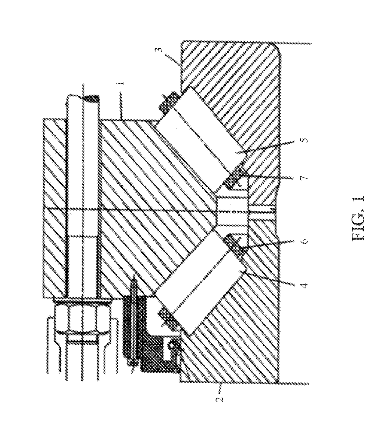
[0017]An example of a bearing that is suitable for supporting the main shaft of a wind turbine is shown in FIG. 1. The bearing must withstand high axial loads as well as radial loads and is executed as a double-row tapered roller bearing. The bearing comprises an outer ring 1 provided with conically shaped first and second outer raceways for a first set 4 and a second set 5 of tapered rollers. The bearing further comprises first and second inner rings 2, 3 which are respectively provided with conically shaped first and second inner raceways for the first and second roller sets 4, 5. In addition, a first cage 6 and a second cage 7 are provided for retaining the rollers of the first and second roller sets respectively. Typically, the cages are formed from segments that abut each other in circumferential direction.

[0018]To provide the necessary stiffness and ensure a long service life, the bearing is preloaded. The axial position of the inner rings 2, 3 relative to the outer ring 1 is ...


PUM


Abstract

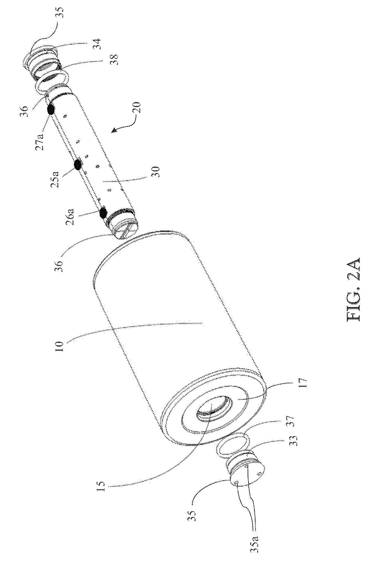
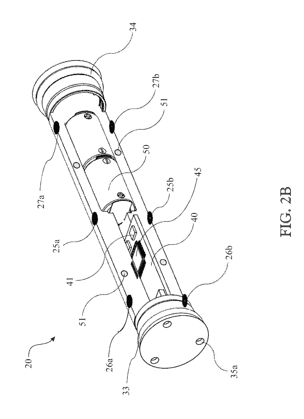
A sensorized roller of a bearing, the sensorized roller having a sensor module located within an axially extending hollow cylindrical bore. The sensor module is equipped with one or more deformation sensors for detecting deformation of the roller bore due to a radial load acting on the roller. The sensor module comprises a rigid housing that is shaped to fit inside the roller bore and is mounted to the roller bore with a small radial clearance between an outer cylindrical surface of the housing an inner cylindrical surface of the bore. Each of the one or more deformation sensors is formed by a proximity sensor that is accommodated at the outer cylindrical surface of the housing. A sensing element of the proximity sensor faces the inner cylindrical surface of the roller bore and measures a radial gap therebetween; the radial gap being indicative of bore deformation.

Description

CROSS-REFERENCE OF RELATED APPLICATIONS[0001]This application claims priority to German patent application no. 102018200048.4 filed on Jan. 3, 2018, the contents of which are fully incorporated herein by reference.TECHNICAL FIELD OF THE PRESENT INVENTION[0002]The present invention relates to the field of load detection in roller bearings and is more particularly directed to a bearing roller with a hollow bore in which one or more sensors are arranged for detecting deformation of the roller bore due to radial load acting the bearing.BACKGROUND OF THE PRESENT INVENTION[0003]An example of a bearing roller of this kind is known from WO 2016 / 016054. A device for detecting a radial load acting on the roller is disclosed. The device comprises a load cell that spans the roller bore diameter and is in fixed contact with diametrically opposite portions of the bore surface. When the roller is radially loaded, the circular cross section of the hollow bore is deformed to an elliptical shape. Und...

Claims


Application Information

Patent Timeline
IPC IPC(8): F16C41/00F16C19/36F16C33/34G01B7/24G01B7/14
CPCF16C41/008F16C19/361F16C33/34G01B7/24G01B7/14F16C2233/00F16C19/522F16J15/06G01L5/0009F16C19/386F16C33/366B65G43/02G01G23/005
Inventor DEN HAAK, NICOLAAS SIMON WILLEMVAN AMERONGEN, GERTJAN
Owner AB SKF
Learn More