
Eureka
For R&D, Eureka makes reading and utilizing patents & technical documents easy.
Eureka AIR
Designed for self-driven R&D workflows. Generate viable solutions, solve complex R&D challenges, empower your innovation with AI.

Eureka Materials
Designed for material experts only. Revolutionize your material R&D, from search, analyze, to developing new materials.

TechResearch
Generate reliable direction feasibility study reports for your R&D in just a few steps.

TechSeek
Discover and master advanced knowledge NOW. Basics, ideas, possibilities, all at once.

TechMind
As an expert in R&D Theories, TechMind can generates customized viable solutions instantly.

TechRisk
Analyze your overall solution with one click, know your potential R&D risks in advance.

TechMonitor
Get weekly tech updates, stay abreast of the latest tech innovations and key insights.
Shift-by-wire system
- Summary
- Abstract
- Description
- Claims
- Application Information
AI Technical Summary
Benefits of technology
Problems solved by technology
Method used
Image

Examples
first embodiment
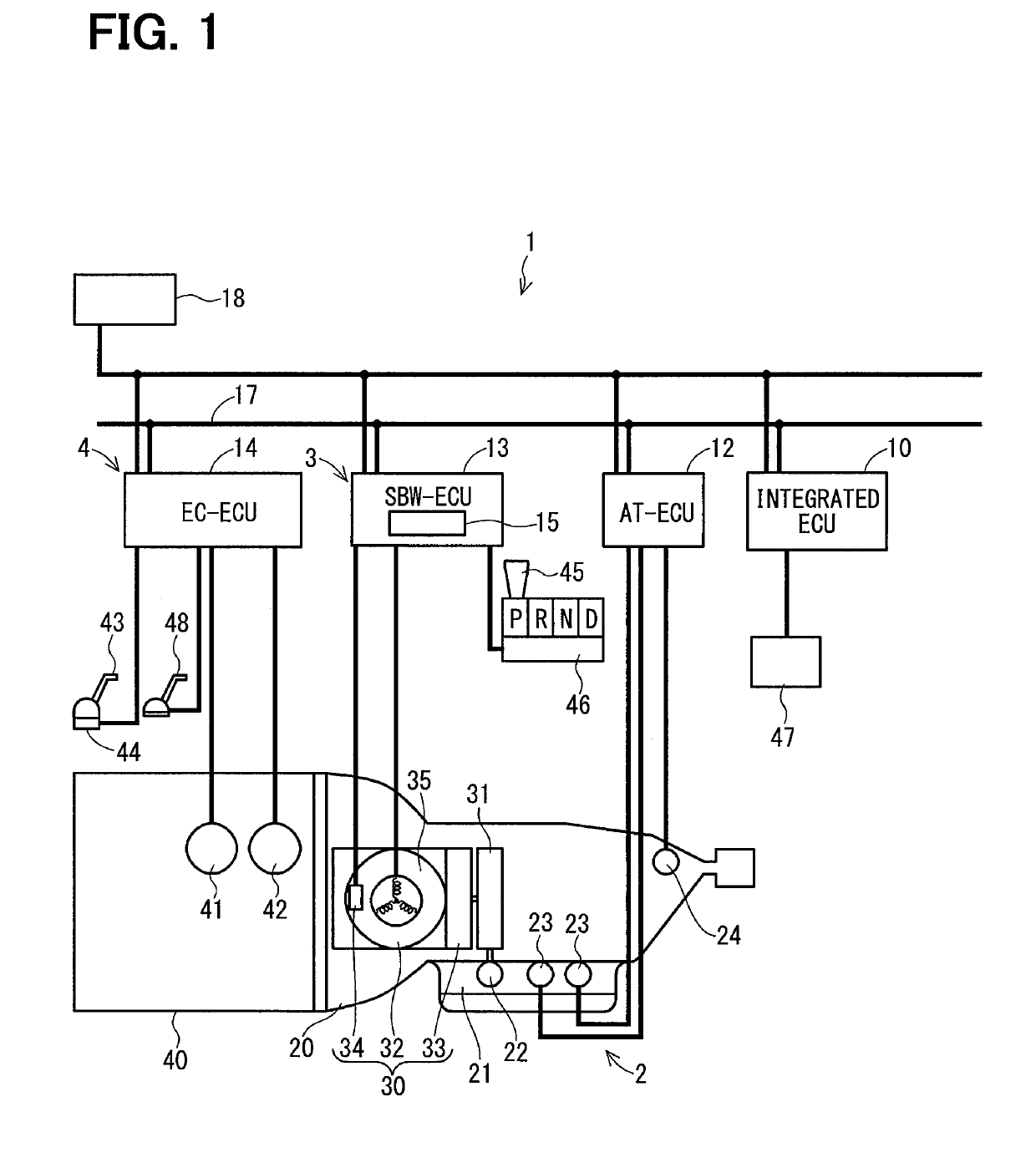
[0051]FIG. 1 shows a vehicle control system 1 including the shift-by-wire system 3 according to the first embodiment.
[0052]The vehicle control system 1, for example, is mounted to a vehicle with four wheels, and includes an automatic transmission control system 2, the shift-by-wire system 3, an engine control system 4 and an integrated ECU 10.
[0053]The automatic transmission control system 2 includes an AT-ECU 12, the shift-by-wire system 3 includes a SBW-ECU 13 as a control unit, and the engine control system 4 includes an EC-ECU 14.
[0054]Each of the AT-ECU 12, the SBW-ECU 13 and the EC-ECU 14 is an electric circuit mainly constituted by a microcomputer. The AT-ECU 12, the SBW-ECU 13 and the EC-ECU 14 are electrically or optically connected with each other via a LAN line 17 in the vehicle.
[0055]The AT-ECU 12, the SBW-ECU 13 and the EC-ECU 14 are electrically connected with a battery 18 that is a power source of the vehicle, and operate by a power supplied from the battery 18.
[0056]...
second embodiment
[0296]A second embodiment is similar to the first embodiment except for a control factor that is a pressing of the brake pedal. In other words, according to the second embodiment, the SBW-ECU does not use the vehicle speed as the control factor.
[0297]Processings of the learning of the reference position of the actuator 30 executed by the SBW-ECU 13 will be described referring to time charts in FIGS. 15 and 16.
[0298]When the brake pedal 48 is pressed while the shift range is the N-range, the shift range is changed to the R-range after the power recovery of the instantaneous interruption of the vehicle power. In the above case, the processing of the learning of the reference position of the actuator 30 executed by the SBW-ECU 13 will be described referring to the time chart in FIG. 15.
[0299]A time point t70 is a power recovery time point of the instantaneous interruption of the vehicle power. ON shown in FIGS. 15 and 16 indicates a pressed state where the brake pedal 48 is pressed, an...
third embodiment
[0339]A third embodiment is similar to the first embodiment except for a control factor that is an accelerator opening degree. In other words, according to the third embodiment, the SBW-ECU does not use the vehicle speed as the control factor.
[0340]Processings of the learning of the reference position of the actuator 30 executed by the SBW-ECU 13 will be described referring to time charts in FIGS. 18 and 19.
[0341]When the accelerator opening degree Ac is less than an opening-degree predetermined value Ar, that is, when Ac30 executed by the SBW-ECU 13 will be described referring to the time chart in FIG. 18. The opening-degree predetermined value Ar is a value that is optionally set, or is calculated by a test value or a simulation.
[0342]A time point t90 is a power recovery time point of the instantaneous interruption of the vehicle power.
[0343]As shown in FIG. 18, the accelerator opening degree Ac is less than the opening-degree predetermined value Ar from the time point t90.
[0344]T...
PUM
 Abstract
Description
Claims
Application Information
 - R&D Engineer
- R&D Manager
- IP Professional
- Industry Leading Data Capabilities
- Powerful AI technology
- Patent DNA Extraction
Browse by: Latest US Patents, China's latest patents, Technical Efficacy Thesaurus, Application Domain, Technology Topic, Popular Technical Reports.
© 2024 PatSnap. All rights reserved.Legal|Privacy policy|Modern Slavery Act Transparency Statement|Sitemap|About US| Contact US: help@patsnap.com