Unlock instant, AI-driven research and patent intelligence for your innovation.

A method for controlling the temperature of a cooling fluid in a cooling system and a cooling system

Inactive Publication Date: 2019-07-04
SCANIA CV AB
View PDF0 Cites 3 Cited by
  • Summary
  • Abstract
  • Description
  • Claims
  • Application Information

AI Technical Summary

Benefits of technology

The technical effect of this patent is to develop a method for controlling the temperature of a cooling fluid in a cooling system for vehicles that optimizes engine efficiency and reduces fuel consumption. This method should be robust and able to quickly actuate valves in the system to quickly optimize the cooling fluid temperature.

Problems solved by technology

This is specifically an issue for manufacturers of heavy vehicles, such as trucks and buses.
If the cooling liquid temperature becomes too high there is a risk that the condenser or other components of the cooling system will be damaged.
However, sufficiently accurate and on the other hand flexible control of the cooling system cannot be obtained by means of thermostats.

Method used


Image

  • A method for controlling the temperature of a cooling fluid in a cooling system and a cooling system
  • A method for controlling the temperature of a cooling fluid in a cooling system and a cooling system
  • A method for controlling the temperature of a cooling fluid in a cooling system and a cooling system

Examples


Embodiment Construction

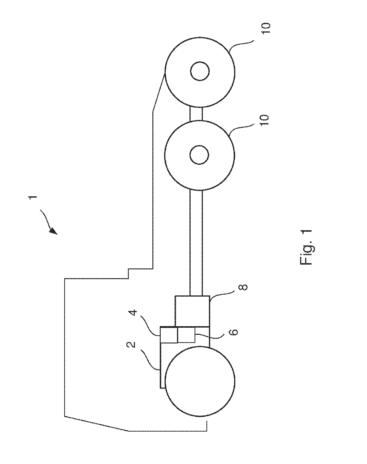
[0035]FIG. 1 schematically shows a side view of a vehicle 1 comprising an internal combustion engine 2, a waste heat recovery system 4 associated with the internal combustion engine 2 and a cooling system 6 connected to the waste heat recovery system 4. The vehicle 1 further comprises a gearbox 8 connected to the driving wheels 10 of the vehicle 1. The vehicle 1 may be a heavy vehicle, e.g. a truck or a bus. The vehicle 1 may alternatively be a passenger car. The vehicle may be a hybrid vehicle comprising an electric machine (not shown) in addition to the combustion engine 2.

[0036]Reference is now made to FIGS. 2 and 3 which schematically illustrate example embodiments of a cooling system of the present invention connected to a waste heat recovery system via a condenser. Each one of FIGS. 2 and 3 schematically shows the waste heat recovery and the cooling systems 4, 6 arranged in fluid connection with an internal combustion engine 2 of a vehicle 1.

[0037]Generally, the cooling system...


PUM


Abstract

Provided is a method for controlling the temperature of a cooling fluid in a cooling system comprising a cooling circuit connected to a condenser of a waste heat recovery system, a cooling pump arranged to circulate a cooling fluid through the cooling circuit and a radiator arranged for cooling the cooling fluid, a bypass circuit, a first and a second valve unit, wherein the first valve unit is arranged to control the flow of cooling fluid through the radiator and the bypass circuit, and the second valve unit controls the flow of cooling fluid passing through the condenser. A condenser-in temperature of the cooling fluid is determined by a first temperature sensor and an engine-in temperature of the cooling fluid is determined by a second temperature sensor. The flow of the cooling fluid is controlled by the first valve unit and / or the second valve unit based on the determined condenser-in and engine-in fluid temperatures.

Description

CROSS-REFERENCE TO RELATED APPLICATIONS[0001]This application is a national stage application (filed under 35 § U.S.C. 371) of PCT / SE2017 / 050837, filed Aug. 22, 2017 of the same title, which, in turn, claims priority to Swedish Application No. 1651213-9, both filed Sep. 9, 2016 of the same title; the contents of each of which are hereby incorporated by reference.FIELD OF THE INVENTION[0002]The present invention relates to a method for controlling the temperature of a cooling fluid in a cooling system coupled with an internal combustion engine of a vehicle, a cooling system, a vehicle comprising such a cooling system, a computer program and a computer program product according to the appended claims.BACKGROUND OF THE INVENTION[0003]Vehicle manufacturers are today striving to increase engine efficiency and reduce fuel consumption. This is specifically an issue for manufacturers of heavy vehicles, such as trucks and buses. One way of improving engine efficiency and fuel consumption is ...

Claims


Application Information

Patent Timeline
IPC IPC(8): F28D21/00F28F27/02
CPCF28D21/0003F28F27/02F28D2021/0094F28F2250/06F01N5/02F01P3/12F01P3/20F01P7/14F02G5/02F16T1/00Y02T10/12F01K9/003F01K23/06F02G5/04F01P2007/146F01K23/065F01P2025/30F01P2060/14F01K9/00
Inventor JOHANSSON, BJORNHOCKERDAL, ERIK
Owner SCANIA CV AB