Apparatus and Method for Arranging Concrete Structure Service Condition Optical Fiber Acoustic Emission Sensing Device

a technology of optical fiber and concrete structure, applied in the direction of instruments, using wave/particle radiation means, analysing solids using sonic/ultrasonic/infrasonic waves, etc., can solve the problems of poor anti-electromagnetic interference capability and short signal transmission, and achieve improved acoustic wave propagation, simple operation, and improved monitoring

Active Publication Date: 2019-07-04
HOHAI UNIV
View PDF9 Cites 1 Cited by
  • Summary
  • Abstract
  • Description
  • Claims
  • Application Information

AI Technical Summary

Benefits of technology

[0018]According to the apparatus for arranging a concrete structure service condition optical fiber acoustic emission sensing device of the present invention, an apparatus for arranging a sensing optical fiber acoustic emission sensing device which integrates a main co-cavity hole, a co-cavity hexagonal hole and a co-cavity circular hole is firstly provided. By creatively providing multi-shaped cavity holes, large and small cavity holes and cavity holes at different positions in the space, multilevel acoustic emission sources with multiple different durations are constructed, acoustic wave propagation is increased, multilevel multiple different durations of optical information in sensing optical fibers are affected, and an important guarantee is provided for better monitoring the service condition of a structural body. The present apparatus is simple in operation, low in monitoring cost, complete in structure, and highly streamlined and automated, and is of great significance in application and promotion of an optical fiber sensing and acoustic emission convergence technology in practical engineering.

Problems solved by technology

The conventional acoustic emission sensors are made of piezoelectric ceramic or piezoelectric crystal materials, which have the disadvantages such as poor anti-electromagnetic interference capability and short signal transmission.

Method used


Image

  • Apparatus and Method for Arranging Concrete Structure Service Condition Optical Fiber Acoustic Emission Sensing Device

Examples


Embodiment Construction

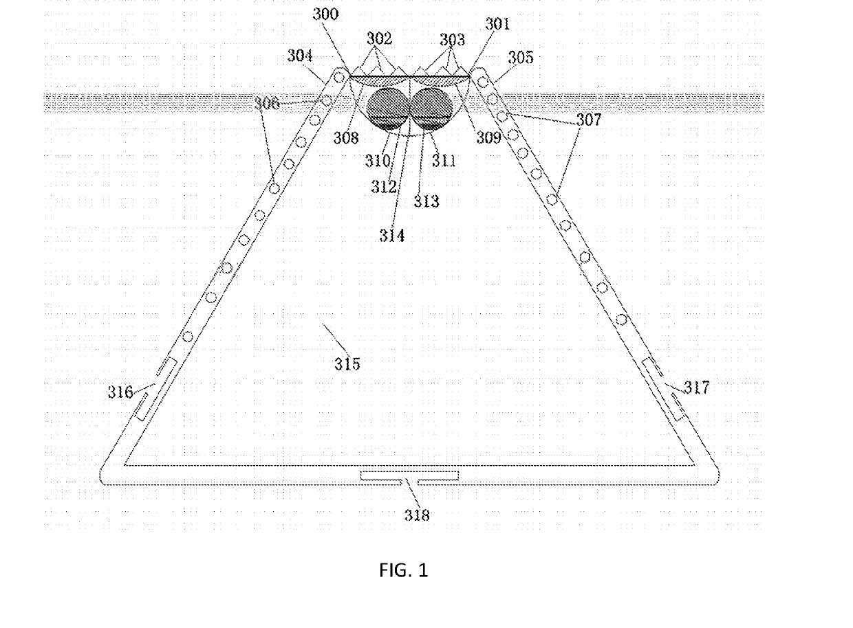
[0021]As shown in FIG. 1, an apparatus for arranging a concrete structure service condition optical fiber acoustic emission sensing device of the present invention includes a bottom plate, and a first side plate 304 and a second side plate 305 fixedly connected to both sides of the bottom plate. The top of the first side plate 304 is connected to the top of the second side plate 305 by an arc-shaped fiber carrying channel, the arc-shaped fiber carrying channel including a first arc-shaped fiber carrying channel 310 having a radian of π / 2 and a second arc-shaped fiber carrying channel 311 having a radian of π / 2. The bottom plate, the first side plate 304, the second side plate 305 and the arc-shaped fiber carrying channel form a main co-cavity hole 315. A first arc-shaped cover 300 and a second arc-shaped cover 301 are hinged to the tops of the first side plate 304 and the second side plate 305 respectively. A first arc-shaped pressing body 308 is fixedly connected to the lower end s...


PUM

PropertyMeasurementUnit
angleaaaaaaaaaa
widthaaaaaaaaaa
lengthaaaaaaaaaa

Abstract

The apparatus comprises a bottom plate, a first side plate (304), and a second side plate (305). The top of the first side plate is connected to the top of the second side plate by an arc-shaped fiber carrying channel (310, 311). A first arc-shaped cover (300) and a second arc-shaped cover (301) are hinged to the tops of the first side plate and the second side plate, respectively. A first arc-shaped pressing body (308) and a second arc-shaped pressing body (309) are fixedly connected to the lower end surfaces. A first sensing optical fiber (312) and a second sensing optical fiber (313) located in the arc-shaped fiber carrying channel are disposed below the first arc-shaped pressing body and the second arc-shaped pressing body respectively. The first arc-shaped cover is connected to the second arc-shaped cover by a locking apparatus.

Description

TECHNICAL FIELD[0001]The present invention relates to an apparatus and method for arranging a concrete structure service condition optical fiber acoustic emission sensing device, and belongs to the field of hydraulic structure health monitoring.BACKGROUND ART[0002]A sensing fiber has both “transmitting” and “sensing” functions. There are many types of sensors based on an optical fiber sensing technology. The same parameter can be measured by different types of sensors, but the core idea of the optical fiber sensing technology is to detect modulation of light from external parameters, which is classified into an intensity modulation type, a phase modulation type, a frequency modulation type, a wavelength modulation type and a polarization state modulation type according to the principle of modulation of light in an optical fiber. With the development of optical information and sensing technology, the optical fiber sensing technology has made great progress, and has advantages in sens...

Claims


Application Information

Patent Timeline
Patent Type & Authority Applications(United States)
IPC IPC(8): G01N29/14G01N29/24
CPCG01N29/14G01N29/2462G01N2291/0232G01H9/004G01N29/04G01N29/2418G01N2291/0258
Inventor SU, HUAIZHIYANG, MENGJIA, QIANGQIANG
Owner HOHAI UNIV
Why Eureka
Try Eureka