Bioprinter design and applications

a bioprinter and design technology, applied in the direction of manufacturing driving means, applying layer means, instruments, etc., can solve the problems of high healthcare costs in the us market, high hardware costs, and inapplicability to biotech related lab automation

Inactive Publication Date: 2019-07-11
ROUSE RICHARD
View PDF0 Cites 6 Cited by
  • Summary
  • Abstract
  • Description
  • Claims
  • Application Information

AI Technical Summary

Problems solved by technology

Typically this type of hardware is very expensive requiring a service contract to maintain over time.
Given the exclusivity, the manufacturer can and does drive the cost up which eventually is passed on to the consumer which factors into the high healthcare costs in the US market.
This is not practical for biotech related lab automation since the printing targets movement can adversely affect the accuracy of the manufacturing process.

Method used


Image

  • Bioprinter design and applications
  • Bioprinter design and applications
  • Bioprinter design and applications

Examples


Embodiment Construction

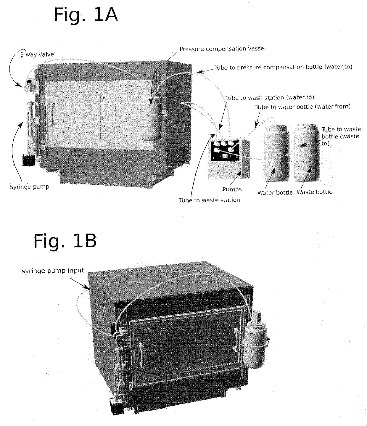
[0007]The described invention consists of a robotic XYZ system for imaging, dispensing liquids and 3D printing. FIG. 1 is an illustration of outside view of the system enclosure. Positioned on the outside of the enclosure are a syringe pump module, tubing and a pressure compensation vessel that is used to control the liquid level in dispensing nozzles (not diagrammed in this figure).

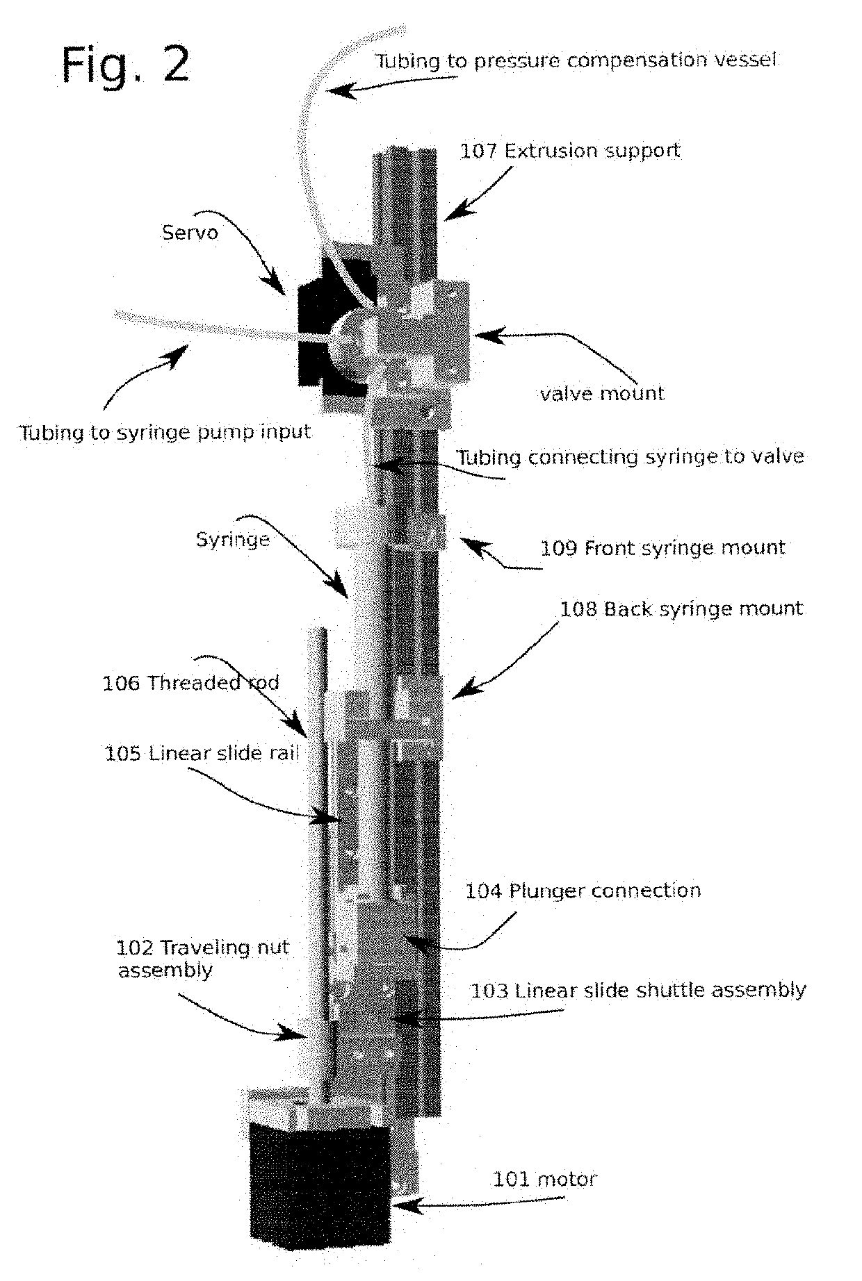
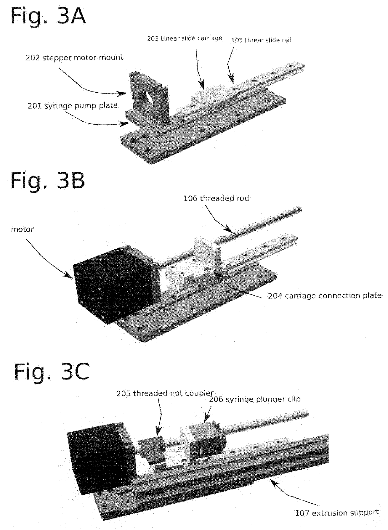
[0008]The syringe pump module is designed to work with different sizes of disposable syringes. The assembly is set up to conveniently remove the syringes so that they can be replaced. Diagrammed in FIG. 2 is an expanded view of a syringe pump module. In order to move the syringe plunger up and down to aspirate or dispense fluid, shown in FIG. 2 is a stepper motor 101, traveling nut assembly 102, threaded rod 106, linear slide rail 105, linear slide assembly 103, plunger connection 104, front syringe mount 109 and back syringe mount 108 that keep the syringe fixed as the syringe plunger moves. The motor 1...


PUM

PropertyMeasurementUnit
diameteraaaaaaaaaa
diameteraaaaaaaaaa
outer diameteraaaaaaaaaa

Abstract

Enclosed is a description of a high throughput 3D printing and imaging system that can be used for multiple laboratory purposes from bioassay fabrication to analysis. This compact system is designed to work with multiple microwell plates and slides. It also contains linear encoders for precise positional control in the XYZ direction. A syringe pump and 3 way select valve configuration and interrelated microfluidics are described and compact stepper motor driven linear actuators for moving tools on the gantry head is also explained. In addition, there is a visualization and sorting area for measuring droplets and for deflecting charged particles magnetized collection tubes. There is also an imaging module for quantifying fluorescence abundance and an analog signal triggered camera that can be synchronized with dispensers that can be used for synchronized imaging and data collection.

Description

BACKGROUND OF INVENTION[0001]The purpose of the described invention is to describe a general purpose laboratory automation platform that can be used for a variety of biotechnological processes so that it can be reconfigured as application requirements change in the laboratory. It addresses an unmet need where in the current market instruments designed to a specific task such as liquid handling or imaging. Typically this type of hardware is very expensive requiring a service contract to maintain over time. The electronics, hardware and software are proprietary to the manufacturer which forces to the consumer to be dependent on the manufacturers support. Given the exclusivity, the manufacturer can and does drive the cost up which eventually is passed on to the consumer which factors into the high healthcare costs in the US market.[0002]The described invention is designed for configuring an open infrastructure for the end user to customize features. The concept is based on open source ...

Claims


Application Information

Patent Timeline
Patent Type & Authority Applications(United States)
IPC IPC(8): B29C64/227B33Y30/00B33Y50/02B29C64/209B29C64/393
CPCB29C64/227B33Y30/00B33Y50/02B29C64/209B29C64/393B01L9/02B01L9/52B01L9/54G01N35/02
Inventor ROUSE, RICHARD
Owner ROUSE RICHARD
Why Eureka
Try Eureka