
Inductor element

a technology of a conductive element and a conductive core, applied in the direction of basic electric elements, inductance with magnetic cores, electrical devices, etc., can solve the problems of downsizing and reducing resistance values, and achieve the effects of reducing resistance values, increasing the density of conductive portions, and favorable mounting strength

Active Publication Date: 2019-07-11
TDK CORPARATION
View PDF13 Cites 8 Cited by
  • Summary
  • Abstract
  • Description
  • Claims
  • Application Information

AI Technical Summary

Benefits of technology

The invention provides an inductor element that can be easily mounted using a land pattern and it is advantageous for downsizing. The element has high mounting strength and reduces resistance value by increasing the density of conductive portions. This is achieved by connecting the element to a land for mounting via planes.

Problems solved by technology

In conventional inductor elements containing a plurality of conductors, however, a land pattern for connecting the conductors has a complicated shape, and there is a problem with downsizing and reduction of resistance value.

Method used


Image

  • Inductor element
  • Inductor element
  • Inductor element

Examples


first embodiment

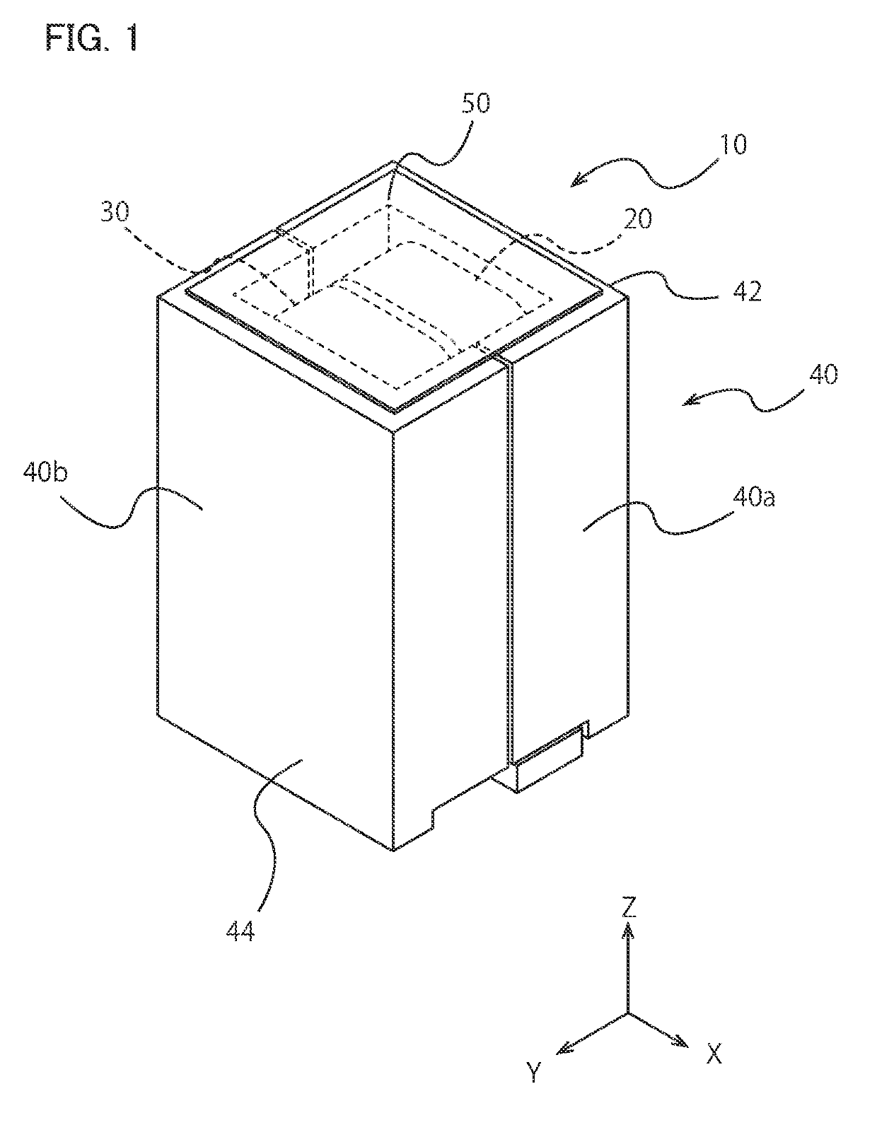
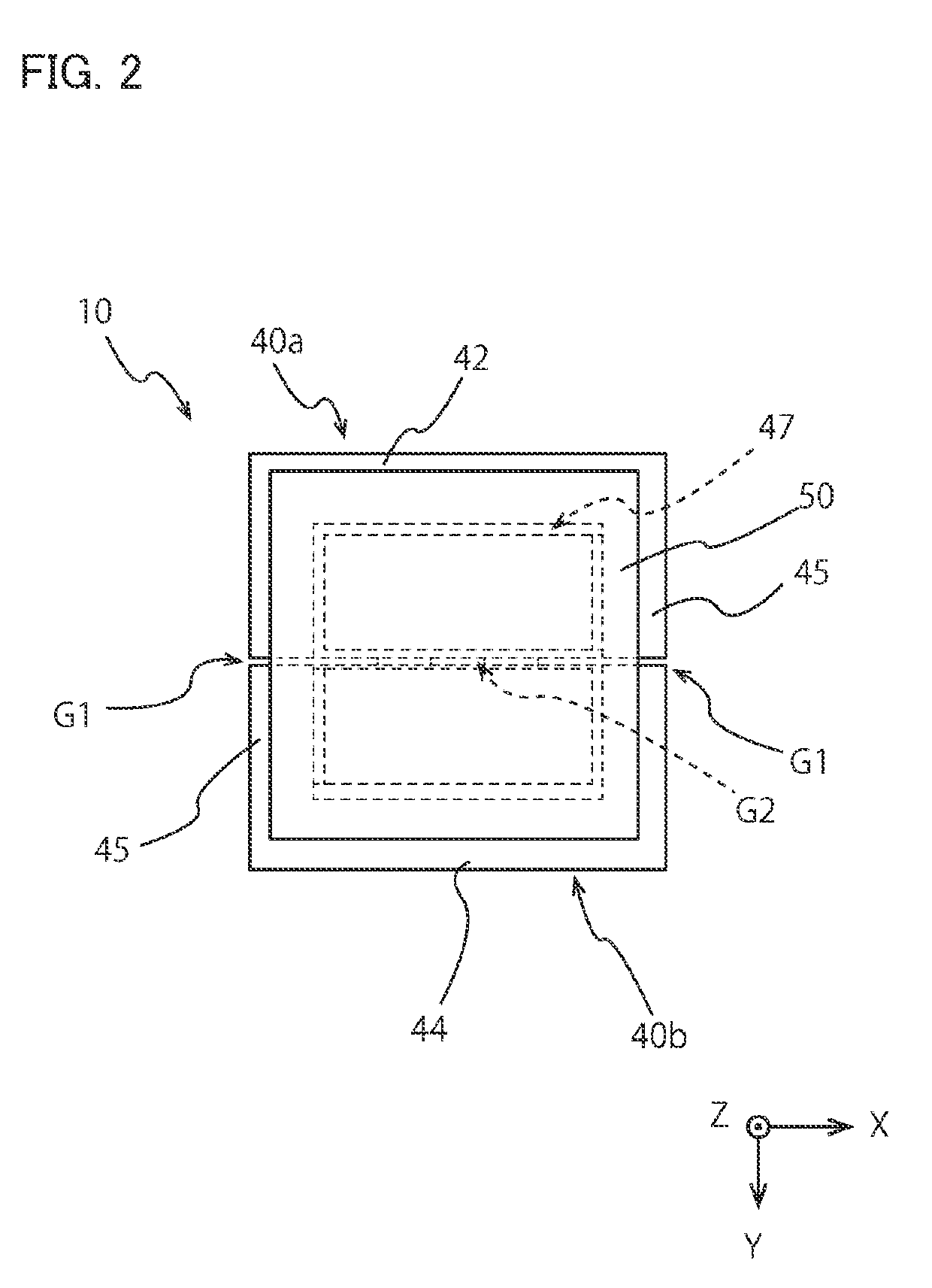
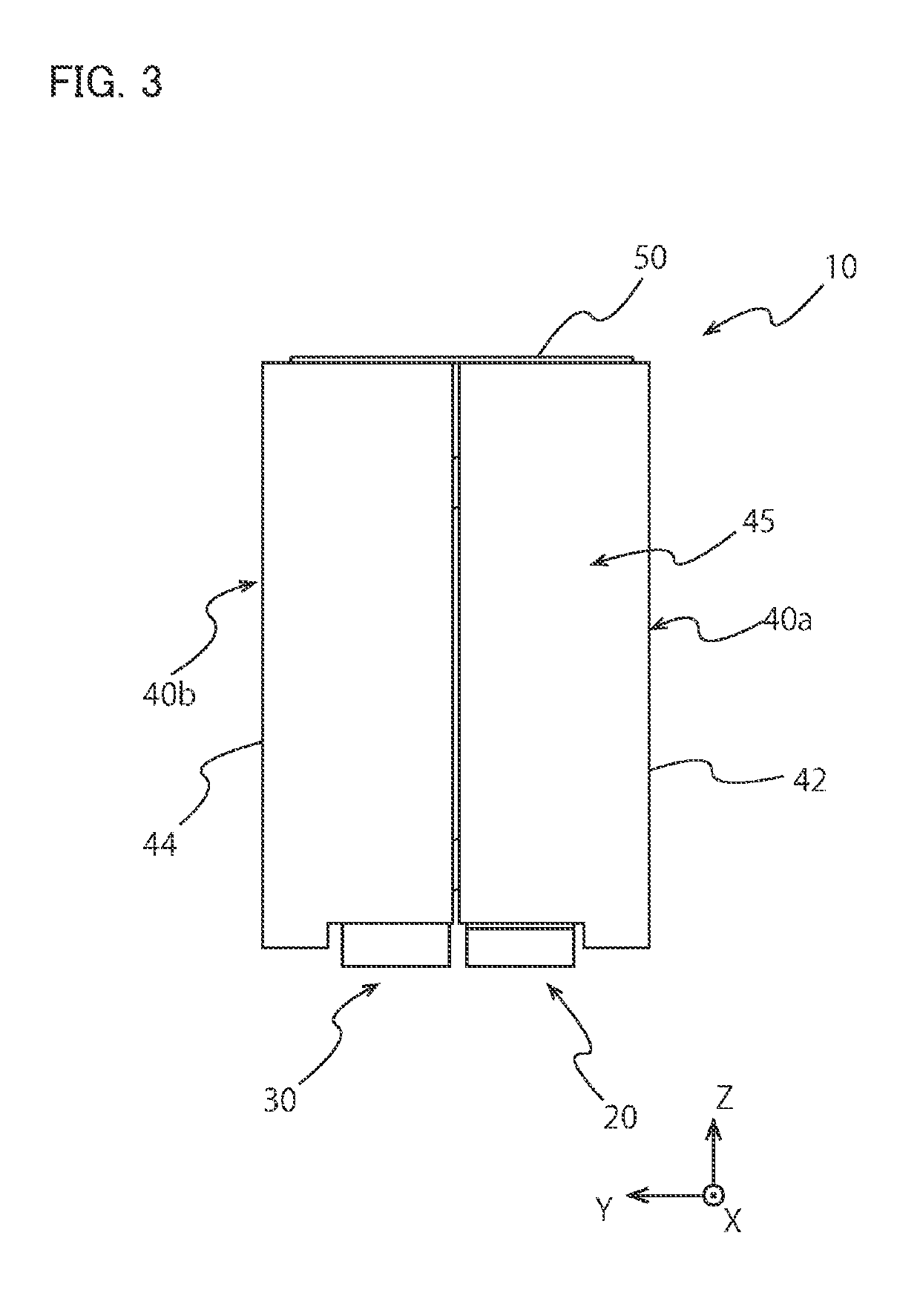
[0048]FIG. 1 is a perspective view of an inductor element 10 according to First Embodiment of the present invention from diagonally above. The inductor element 10 has a roughly cuboid outer shape and is used by being mounted on a mount board with a posture where mount surfaces 24a, 26a, 34a, and 36a forming the bottom of the inductor element 10 in the negative side of the Z-axis direction (see FIG. 5) face lands. In the explanation of the inductor element 10, the Z-axis direction is a normal direction of the a mount surface, the X-axis direction is a perpendicular direction to the Z-axis direction and is a parallel direction to first and second side-wall portions 42 and 44 of a magnetic core 40, and the Y-axis direction is a perpendicular direction to the Z-axis direction and is a normal direction of the first and second side-wall portions 42 and 44 of the magnetic core 40.

[0049]As shown in FIG. 1, the inductor element 10 includes the magnetic core 40 and first and second conductive...

second embodiment

[0079]FIG. 11 is an exterior view of an inductor element 110 according to Second Embodiment of the present invention. The inductor element 110 is similar to the inductor element 10 shown in FIG. 1 except that no upper opening is formed in a magnetic core 140, and that first and second conductive portions 120 and 130 housed in the magnetic core 140 have different detailed shape. Thus, the inductor element 110 is explained in terms of only differences from the inductor element 10 and is not explained in terms of common matters with the inductor element 10.

[0080]As shown in FIG. 11, the magnetic core 140 of the inductor element 110 is formed by combining first and second core portions 140a and 140b (different members). As shown in FIG. 11 and FIG. 12, side circumferential portions 145 connect a first side-wall portion 142 of the first core portion 140a and a second side-wall portion 144 of the second core portion 140b at both sides of the magnetic core 140 in the X-axis direction and a...


PUM

PropertyMeasurementUnit
lengthaaaaaaaaaa
cross-sectional areaaaaaaaaaaa
conductiveaaaaaaaaaa

Abstract

An inductor element includes a first conductive portion, a second conductive portion, and a magnetic core. The first conductive portion includes a first round-about portion, a first mount portion, and a second mount portion. The second conductive portion includes a second round-about portion, a third mount portion, and a fourth mount portion. The magnetic core houses at least a part of the first and second conductive portions so that each mount surface of the first to fourth mount portions is exposed from one side of the magnetic core. The first and second conductive portions are arranged so that the first and second directions are substantially parallel and opposite to each other. The first and third mount portions are at least partially overlapped with each other in a third direction perpendicular to the first and second directions.

Description

BACKGROUND OF THE INVENTION[0001]The present invention relates to an inductor element used for electronic circuits or so.[0002]As inductor elements responsible to a high electric current, having a comparatively low L value, and required for high magnetic saturation characteristics, proposed is an inductor element where a conductor having less than 1 T is covered with a magnetic material. As one of these inductor elements, also proposed is an inductor element containing a plurality of mutually independent conductors. In such an inductor element containing a plurality of conductors, the conductors are electrically connected via a mount board, and an inductance value similar to that of an element with a conductor having 1 T or more can be achieved.[0003]Patent Document 1: WO2006070544 (Al)BRIEF SUMMARY OF INVENTION[0004]In conventional inductor elements containing a plurality of conductors, however, a land pattern for connecting the conductors has a complicated shape, and there is a pr...

Claims


Application Information

Patent Timeline
Patent Type & Authority Applications(United States)
IPC IPC(8): H01F27/26H01F27/28H01F27/02
CPCH01F27/266H01F27/2823H01F27/022H01F3/14H01F17/04H01F27/263H01F27/2852H01F27/306
Inventor WANG, CHENSUGIMOTO, SATOSHI
Owner TDK CORPARATION
Learn More