Augmented Bypass Catheter

Active Publication Date: 2019-07-18
WALZMAN DANIEL EZRA
View PDF2 Cites 3 Cited by
  • Summary
  • Abstract
  • Description
  • Claims
  • Application Information

AI Technical Summary

Benefits of technology

[0011]While the prior art teaches the during catheter-assisted thrombolysis treatment, a catheter is guided through blood vessels to the location of the blood clot. The catheter will deliver special clot dissolving medicine called thrombolytics to help dissolve the clot. The catheter such as the Ekos device additionally has an ultrasound element to be used in conjunction with the thrombolytic medications to help break up the clot. Said Ekos device lacks the bypass element to help provide immediate reperfusion. The present invention surmounts the lack of immediate reperfusion associated with the Ekos device, by providing immediately restoring the flow of blood to an organ or tissue. In the case of many pulmonary emboli, this bypass element can also immediately relieve strain on the heart created by resistance to outflow.
[0012]The bypass catheter disclosed in in Ser. No. 15/932,911 lacks an adjunctive energy source to help break up clot and help bound fibrin release to better accept lytic medications. The addition of the energy source such as an ultrasound component to the Walzman bypass catheter will facilitate breaking up the clots, requiring lower doses of lytics, over shorter times, and with better net effect.
[0013]It should also be noted that the prior art discloses ultrasound-assisted catheter-directed low-dose thrombolysis delivers the efficacy

Problems solved by technology

Acute intermediate-risk pulmonary emboli in normotensive patients with ventricle (particularly right ventricle) dysfunction present the clinician with a pr

Method used


Image

  • Augmented Bypass Catheter
  • Augmented Bypass Catheter
  • Augmented Bypass Catheter

Examples


Example

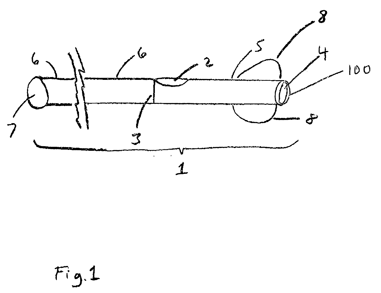
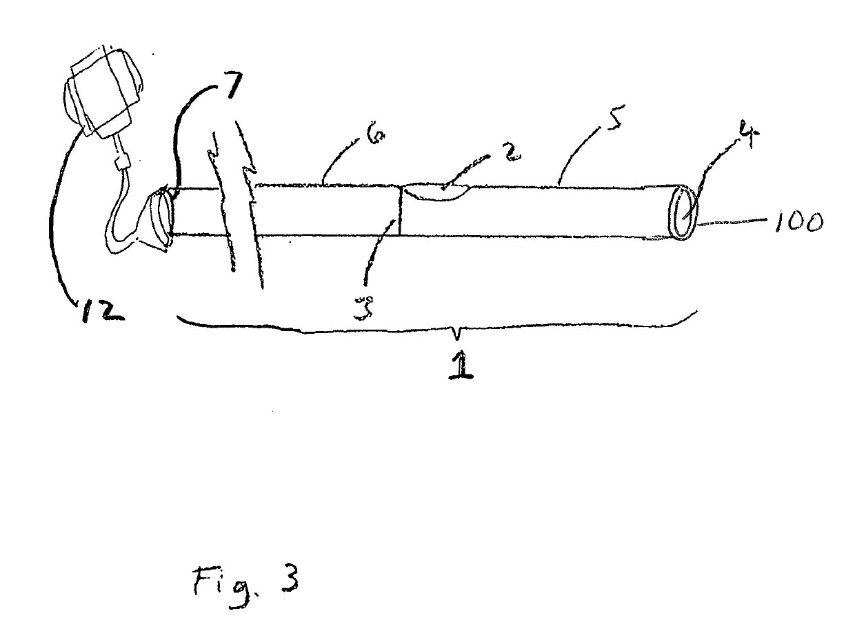
[0020]The present invention discloses the addition of an energy source such as ultrasound transition system to a Walzman bypass catheter Ser. No. 15 / 932,911.

[0021]The energy tipped bypass catheter is composed of the following elements: an energy transmitter, a structure to mount said transmitter to said bypass catheter and an activation element. Said ultrasound transition system or other energy source is designed to break up clot and, in some iterations, to help break up calcium, like a lithotripsy device.

[0022]In an optional embodiment said ultrasound transition system can have a diagnostic ultrasound. However, in the preferred embodiment said ultrasound transition system is designed to break clots, as opposed to acting as a therapeutic device. The diagnostic ultrasound element is optional embodiment.

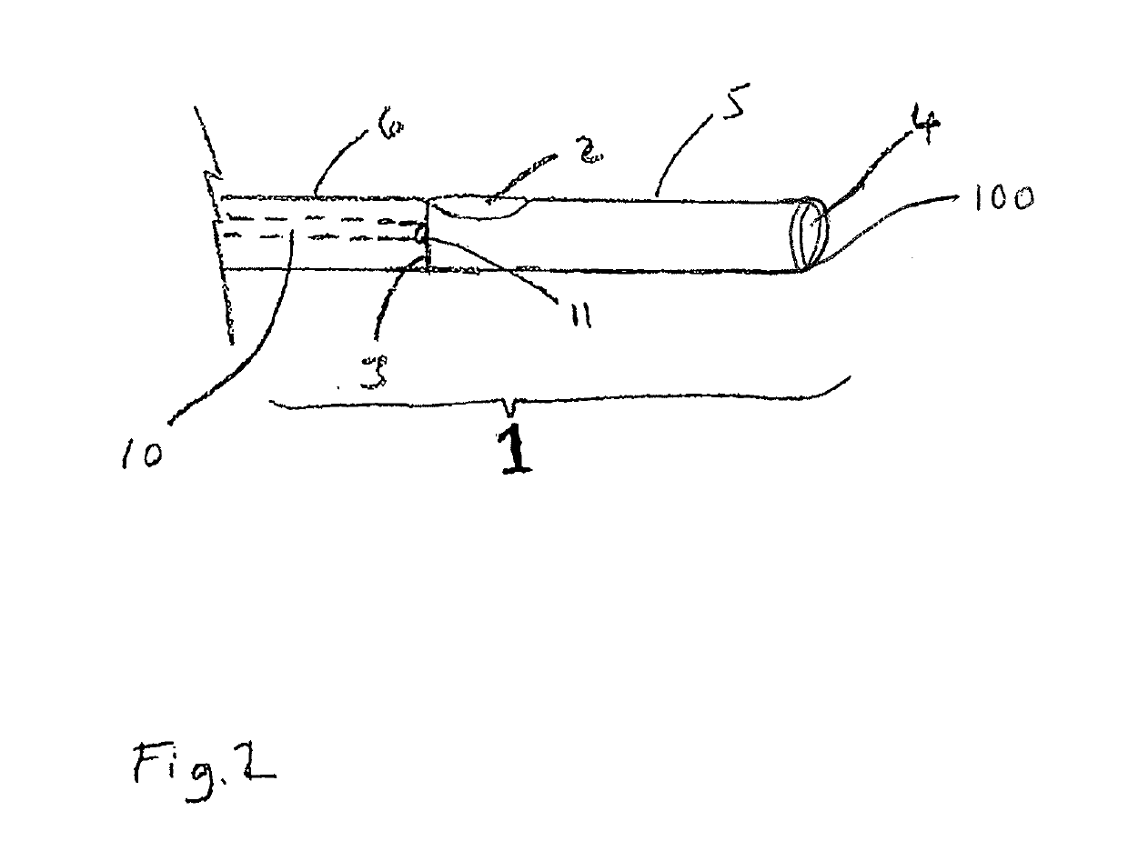
[0023]The temporary balloon element, when present on the bypass catheter, is composed of a catheter with at least one distal end hole, at least one bypass window proximal to said end h...


PUM


Abstract

An innovative medical device that permits rapid, minimally invasive restoration of blood flow across a vascular blockage. A method employing said device, allowing for lysis or removal of said blockage. Said removal of said blockage is facilitated by either or both mechanical and energy-emission maceration. Said device creates a temporary bypass using longitudinal structure configured for insertion into the blood vessel and adapted to deliver a side hole to a target area. The side hole defines a distal first segment and a proximal second segment with a lumen to allow blood flow therethrough to the distal end hole. In an alternate embodiment, a slide-able outer sheath can cover the side hole to permit reversal of blood flow from the distal end hole to a proximal end hole located outside a patient's body by means of an aspiration controller. Alternate embodiments include an optional anchoring balloon, a macerating stent or wires, perforations for fluid delivery, and a backflow valve.

Description

CROSS-REFERENCE(S)[0001]This is a continuation-in-part application claiming the benefit of priority to U.S. Non-Provisional application Ser. No. 15 / 932,911 filed May 18, 2018, and Ser. No. 15 / 732,953 filed Jan. 16, 2018, the entire contents of which are incorporated by reference.BACKGROUND OF THE INVENTIONField of the Invention[0002]The present invention relates generally to medical device placed in a minimally invasive manner, most often percutaneous and endovascular; specifically, to a bypass catheter to ameliorate ischemic injury employing an energy generated tipped bypass catheter.Discussion of the Prior Art[0003]The use of devices in conjunction with medical procedures for controlling blood flow in a blood vessel is taught by the prior art. Among the most common is a balloon catheter. The balloon catheter, such as taught in the prior art, may be used to achieve isolation of a body part from its blood supply.[0004]One of the problems associated with using balloons is that althou...

Claims


Application Information

Patent Timeline
IPC IPC(8): A61M25/00A61M25/10
CPCA61M25/10A61M25/007A61M5/14A61M2025/0073A61M2025/1095A61M2025/0076A61N7/00A61M2025/105A61B17/12136A61B17/3207A61B2017/22079A61B2017/22084
Inventor WALZMAN, DANIEL EZRA
Owner WALZMAN DANIEL EZRA
Why Eureka
Try Eureka