Method for predicting knock, method for suppressing knock, and engine system

Active Publication Date: 2019-07-25
MAZDA MOTOR CORP
View PDF11 Cites 6 Cited by
  • Summary
  • Abstract
  • Description
  • Claims
  • Application Information

AI Technical Summary

Benefits of technology

The patent text discusses the issue of high engine rotational speeds causing intense knocks that can damage the engine and reduce its reliability. These knocks can also occur in engines with high compression ratios, hindering fuel efficiency improvement. The technical effect of the patent is to provide a solution to prevent damage and improve engine reliability and fuel efficiency.

Problems solved by technology

A knock is an abnormal noise generated during an operation of an engine, and is particularly seen as a problem in a spark-ignition engine.
Occurrence of the knock affects user's comfort or reliability of the engine.
Such an intense knock is likely to damage the engine over time, reducing the reliability of the engine.
Also, the intense knock tends to occur in an engine with a high compression ratio, preventing improvement of fuel efficiency.
However, this method reduces a substantial compression ratio and is disadvantageous in terms of improvement of fuel efficiency.
Since the ignition timing is retarded after occurrence of the knock is detected, the inventors have determined that this method is unsuitable for suppressing a sudden intense knock that does not occur frequently.
The engine in Japanese Patent Laid-Open No. 2012-41846 needs to perform two combustions during one combustion cycle, increasing the number of components and making the engine structure and control system more complex.
It is difficult to stably perform the two combustions by ignition at a high rotational speed of the engine with a short combustion time.
Thus, the engine in Japanese Patent Laid-Open No. 2012-41846 is unsuitable for suppressing an intense knock.
The intense knock tends to occur when the engine is operated in a high load and high rotation operating range.

Method used


Image

  • Method for predicting knock, method for suppressing knock, and engine system
  • Method for predicting knock, method for suppressing knock, and engine system
  • Method for predicting knock, method for suppressing knock, and engine system

Examples


Embodiment Construction

[0044]Now, an embodiment of the present disclosure will be described in detail with reference to the drawings. However, the descriptions mentioned below are merely illustrative, and do not limit the present disclosure, application or use thereof.

[0045]

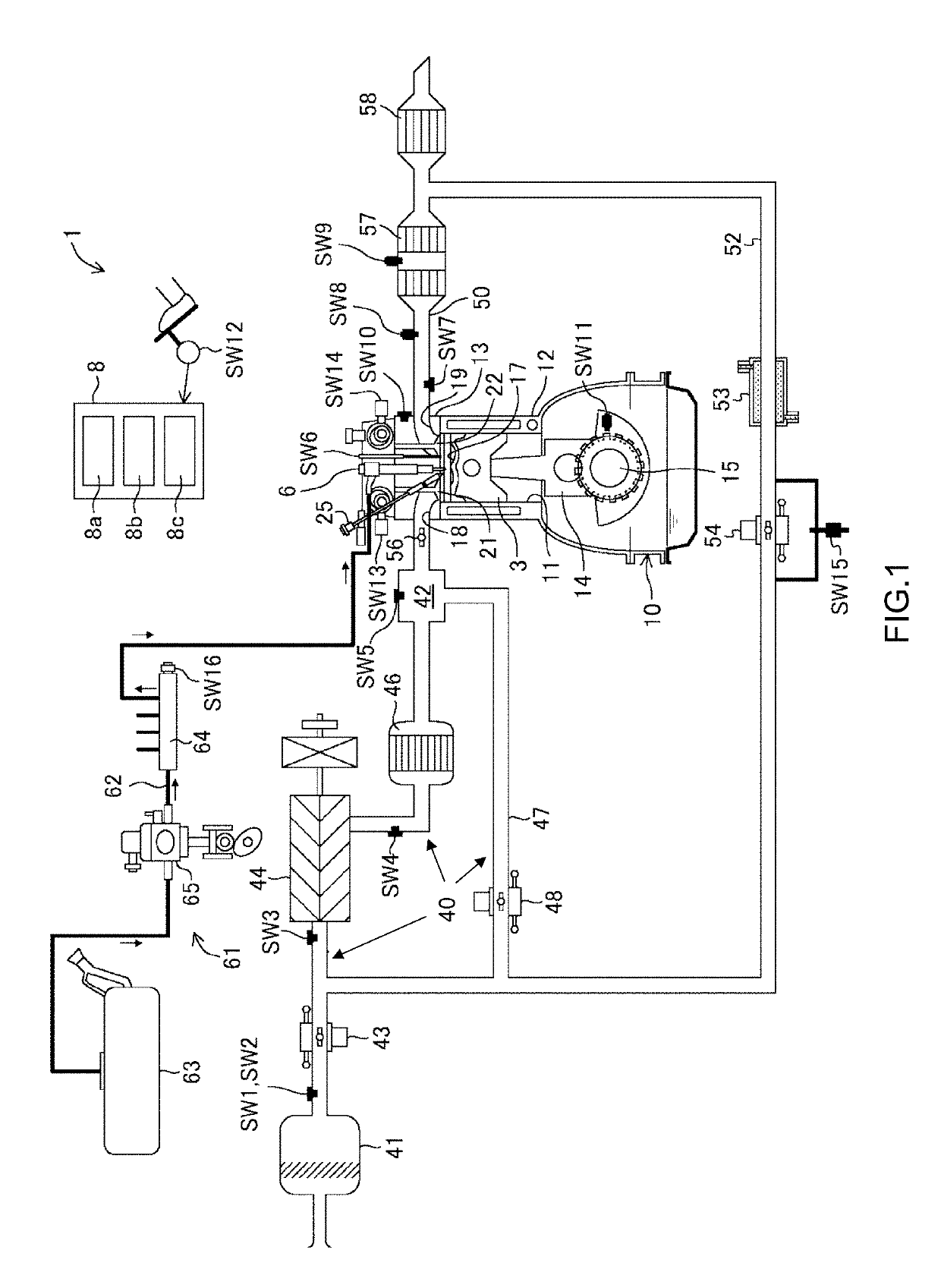
[0046]FIG. 1 shows an engine 1 to which the disclosed technique is applied. This engine 1 is mounted in an automobile. The automobile is propelled by operation of the engine 1 using fuel containing gasoline. The fuel for the engine 1 may be pure gasoline or gasoline containing bioethanol or the like. Specifically, the fuel for the engine 1 may be any fuel, according to an embodiment, as long as it is liquid fuel containing at least gasoline. However, any desired type of fuel may be used with the disclosure including both liquids and gases, such as propane.

[0047]The engine 1 performs combustion (also referred to as SPCCI (“Spark Controlled Compression Ignition”) combustion) that is a combination of spark ignition (SI) combustion and com...


PUM


Abstract

A method and system for predicting the occurrence of a knock which will have a predetermined intensity or higher (intense knock) in an engine that burns an air-fuel mixture of gasoline fuel. The pressure in a combustion chamber is detected during an initial stage of combustion. This pressure is compared with a preset reference value to determine whether or not the cylinder inner pressure exceeds the reference value during the combustion. When the cylinder inner pressure exceeds the reference value, it is predicted that the intense knock will occur before an end of the combustion. If the intense knock is predicted, additional fuel or other material can be injected into the combustion chamber to prevent the occurrence of the intense knock.

Description

CROSS REFERENCES TO RELATED APPLICATIONS[0001]This application claims priority to Japanese Patent Application 2018-007852, filed on Jan. 22, 2018, which is incorporated herein by reference. This application is also related to co-pending U.S. application Ser. No. ______, (Attorney Docket Number 11621US01) which is entitled “Method for Suppressing Knock and Engine System,” filed concurrently with the present application, which is also incorporated by reference.BACKGROUNDTechnical Field[0002]The disclosed technique relates to a technique for predicting occurrence of an intense knock (also referred to as knocking) having a predetermined intensity or higher in an engine, and suppressing the intense knock based on the prediction.Description of the Related Art[0003]A knock is an abnormal noise generated during an operation of an engine, and is particularly seen as a problem in a spark-ignition engine. Knocking occurs when combustion of some of the air / fuel mixture in a cylinder does not re...

Claims


Application Information

Patent Timeline
IPC IPC(8): F02D35/02F02D41/22F02D41/14G01L23/22F02D33/00
CPCF02D35/027F02D41/22F02D41/1495G01L23/227F02D33/006F02D2250/14F02D2200/0602F02D37/02F02D41/405F02P5/152F02D41/3041F02D35/023F02D2041/1412
Inventor SHISHIME, KOUJIKOHATA, TAKASHITSUMURA, YUICHIROTANAKA, DAISUKEMAIGUMA, TAIKI
Owner MAZDA MOTOR CORP
Why Eureka
Try Eureka