Filter element

a filter element and fluid technology, applied in the direction of filtration separation, dispersed particle separation, separation process, etc., can solve the problems of high filtering capacity and long service life, and achieve the effect of reducing pressure loss, reducing height, and increasing the capacity to absorb contaminants

Active Publication Date: 2019-08-01
HYDAC FILTER SYST
View PDF3 Cites 3 Cited by
  • Summary
  • Abstract
  • Description
  • Claims
  • Application Information

AI Technical Summary

Benefits of technology

[0007]The shape of the filter liner that is provided according to the invention, which may, for example, be designed such that the outer and / or inner liner surface of the filter liner extends conically, opens up the opportunity to adapt the filter liner, or more accurately, the structure of the filter layers that form the filter liner, optimally to the varying pressure and flow conditions that occur in the different regions between the end caps. For example, the fact that a higher or lower static pressure exists close to one of the end caps, can be accommodated through a greater height of the folds and the resultant thickening of the filter liner. In this respect, the outer diameter of the filter liner at one or the other end cap can be made greater than in the vicinity of the other end cap. This arrangement can achieve a more even flow through the filter, which results in a low pressure loss at reduced turbulence, resulting, in turn, in a high filtering capacity and a long service life.
[0009]That inflow of the unfiltrate from the direction of one of the end caps provides the particular advantage that the height of the filter pleats changes in that it increases in the direction towards the closed end cap. As a result of that increased thickness of the filter liner in the vicinity of the closed end cap, the increased dynamic pressure level is taken into account, which increased pressure is present in the vicinity of the closed end cap when unfiltrate is fed in from the other, open end cap.
[0013]The outer diameter of the filter liner preferably increases from the open end cap towards the closed end cap. When feeding unfiltrate from the upper end cap, the cone shape that tapers from bottom to top is advantageous for the flow of the filter medium.
[0014]When forming the pleated filter liner by folding the filter layers, the process followed may be such that, to pleats of a first kind which, due to their height, make up the majority of the thickness of the filter element. Pleats of a second kind are added, preferably alternating, and are lower in height than those of the first kind. This type of folding pattern, also called M-pleat or W-pleat, has advantages with respect to the configuration of the filter liner according to the invention, such as lower pressure losses, increased capacity to absorb contaminants and an increased security against a kind of “blockage”. Such disadvantages can occur in conventional filter elements through immediate contact between effective pleat surfaces, depending on the flow conditions.

Problems solved by technology

This arrangement can achieve a more even flow through the filter, which results in a low pressure loss at reduced turbulence, resulting, in turn, in a high filtering capacity and a long service life.

Method used


Image

  • Filter element
  • Filter element
  • Filter element

Examples


Embodiment Construction

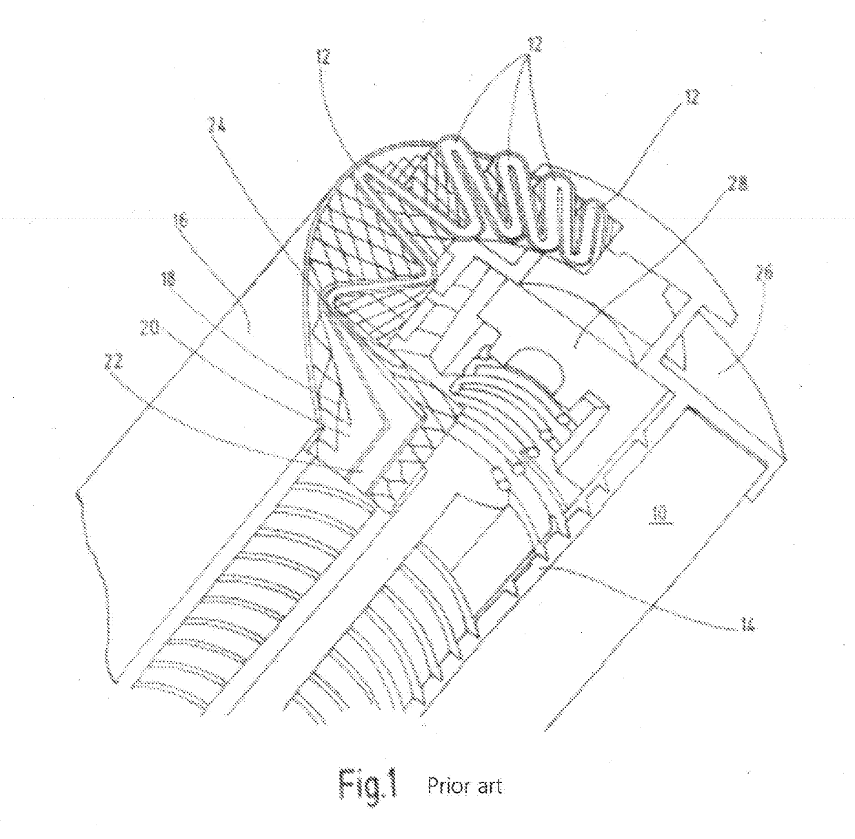
[0027]The filter element that is partially illustrated in FIG. 1, which constitutes the prior art, has a filter liner 10 as the filter material with a predefinable surface area and predefinable filter characteristics. The filter liner 10 is pleated, as illustrated in FIG. 1, with individual filter pleats 12, which extend in a tight package sequence between an inner fluid-permeable support tube 14 and an outer cylindrical casing 16, which is likewise fluid-permeable. The casing 16 may be formed of a mesh structure made from plastic or stainless steel or similar material. For the sake of a clearer depiction, the individual filter pleats 12 are depicted slightly pulled apart in the left, upper part of FIG. 1. The individual layer structure of the pleated filter liner 10 is revealed from the partial depiction facing the observer.

[0028]In the case of filter elements of this kind, the filter liner 10 typically comprises a first support layer 18, a second layer 20 as a protective nonwoven,...


PUM

PropertyMeasurementUnit
thicknessesaaaaaaaaaa
outer diameteraaaaaaaaaa
thicknessaaaaaaaaaa

Abstract

A filter element for fluids, in particular for hydraulic fluid, has a foldable filter casing (10) with at least one filter layer (18, 20, 22, 24) extending between two end caps (26, 32). To vary in regions the thickness of the filter casing (10), the height (h1) of each filter fold (12, 44) increases from one end cap (26) to the other end cap (32). Alternatively, with the filter fold height (h1) being maintained, the outer diameter (40) of the filter casing (10) varies in the direction of one of the end caps (26, 32).

Description

REFERENCE TO RELATED APPLICATION[0001]This application is a Divisional application of U.S. patent application Ser. No. 14 / 779,583, filed Sep. 24, 2015, the entire subject matter of which is incorporated by reference.FIELD OF THE INVENTION[0002]The invention concerns a filter element for fluids, in particular for hydraulic fluids, having at least one foldable filter liner with at least one filter layer. The filter liner extends between two end caps.BACKGROUND OF THE INVENTION[0003]Filter elements of this kind are customary. Such filter elements are widely used in conjunction with fluid systems of all kinds for filtering processing fluids, compression fluids such as hydraulic oils, liquid fuels and lubricants, as well as for the treatment of liquid media and the like. Fluid systems, in which the filter elements are used, provide in many instances only a limited amount of space for the installation or removal of those system components that contain the respective filter candle-shaped f...

Claims


Application Information

Patent Timeline
Patent Type & Authority Applications(United States)
IPC IPC(8): B01D29/33B01D46/52B01D29/23B01D35/00B01D46/24
CPCB01D29/333B01D46/522B01D29/232B01D35/005B01D46/2411B01D2201/122B01D2275/201B01D2201/02
Inventor SCHUNK, ANDREASSCHNEIDER, DOMINIC
Owner HYDAC FILTER SYST
Why Eureka
Try Eureka