Measurement system for aquatic environments comprising a surface vessel and a submersible device

a measurement system and aquatic environment technology, applied in the field of underwater measurement systems, can solve the problems of reducing in proportion the space usable for the crew, thermal shock and/or unbalance liable to be harmful to the measurement device and/or the quality of the measuremen

Active Publication Date: 2019-08-01
EXAIL
View PDF4 Cites 2 Cited by
  • Summary
  • Abstract
  • Description
  • Claims
  • Application Information

AI Technical Summary

Benefits of technology

The present invention proposes a system for measuring aquatic environments using an underwater machine that can be stored in a vessel and later removed for use. The underwater machine can be a submersible machine with propulsion and guiding means, and a sensor package for taking measurements. The vessel can have a crew or no crew, and can be wire-guided or autonomous. The underwater machine can be stored in the vessel's hull and remain submerged during storage. The system also includes a link cable for power and data exchange between the underwater machine and the vessel. The underwater machine can be designed with a working load enclosure that can be pivoted between a retracted position and an extended position. The system allows for the efficient and safe storage and use of the underwater machine in a vessel.

Problems solved by technology

Once the measurements performed, the measurement devices are brought back on board the vessel, on an above-water deck of the latter, which entails relatively long operations, liable to be dangerous both for the crew and for the measurement devices themselves due to rocking, shocks... Moreover, a storage space must be provided for the measurement devices, which reduces in proportion the space usable for the crew.
Furthermore, the passage from the aquatic environment to the open air, and vice versa, causes thermal shocks and / or unbalances liable to be harmful for the measurement devices and / or the quality of the measurements.

Method used


Image

  • Measurement system for aquatic environments comprising a surface vessel and a submersible device
  • Measurement system for aquatic environments comprising a surface vessel and a submersible device
  • Measurement system for aquatic environments comprising a surface vessel and a submersible device

Examples


Embodiment Construction

[0078]The following description, in relation with the appended drawings given by way of non-limitative examples, will permit to understand in what consists the invention and how it may be made.

[0079]In the appended drawings:

[0080]FIG. 1 shows a perspective view of a measurement system with a vessel and an underwater machine wire-guided in phase of remote use of the underwater machine, a winder / unwinder for the link cable between the vessel and the underwater machine being visible on the rear portion of the vessel deck,

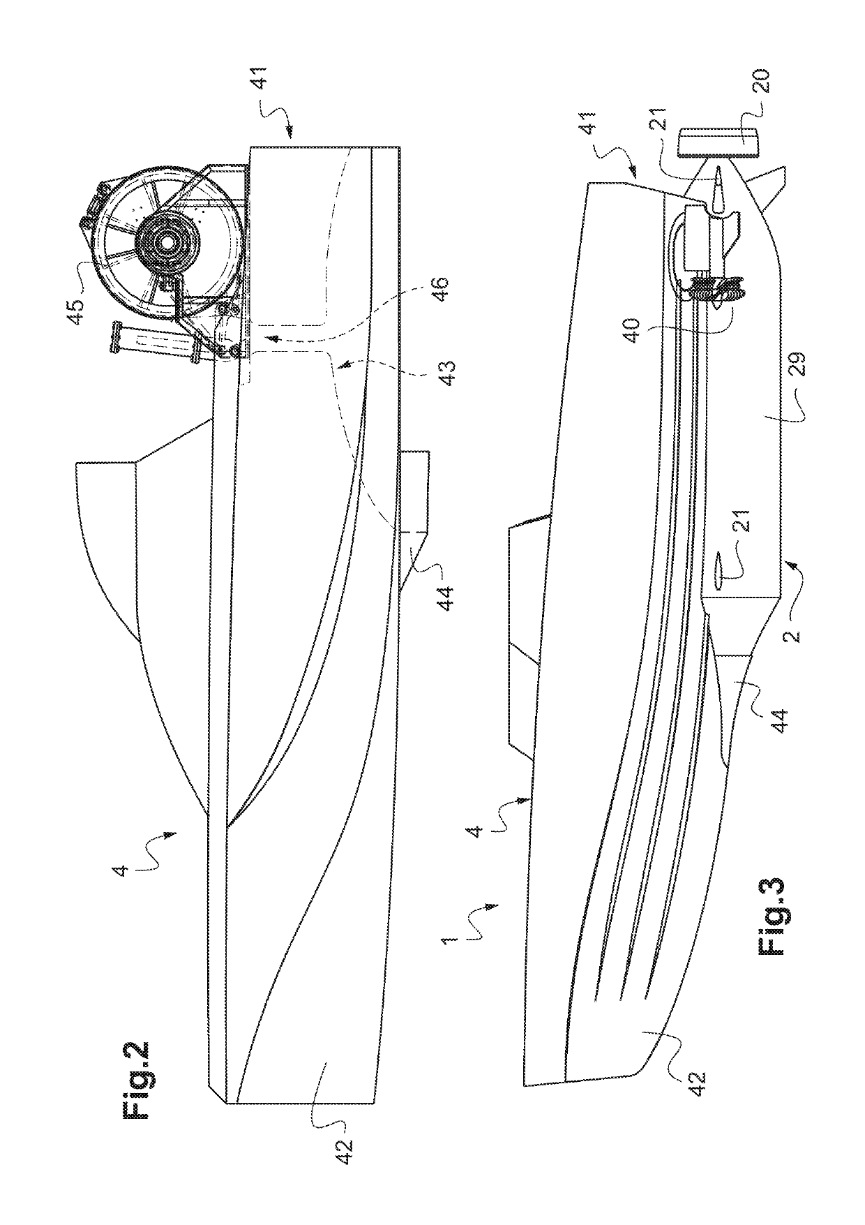
[0081]FIG. 2 shows a lateral view of the vessel of the system of FIG. 1 and of its link-cable winder / unwinder,

[0082]FIG. 3 shows a lateral view of a measurement system with other examples of vessel and underwater machine in phase of storage of the underwater machine in a recess of the vessel hull, the link-cable winder / unwinder being not visible inside the vessel,

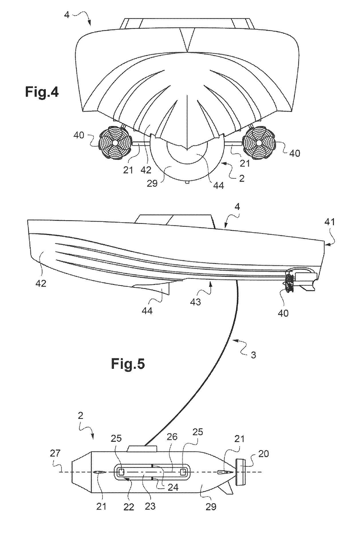
[0083]FIG. 4 shows a front view of the measurement system with vessel and underwater machine of FIG. 3, sti...


PUM


Abstract

Disclosed is a measurement system for aquatic environments, including a surface vessel and a submersible device, the submersible device including a hull, propulsion, guide, and sensors for taking measurements. The submersible device can either be launched from the vessel in order to then maneuver underwater independently of the vessel during a remote deployment phase, or be stored in a vessel during a non-deployment phase, the vessel including at least one hull and propulsion and guide, the at least one hull of the vessel including a submerged portion located below a waterline. The submerged portion of the at least one hull of the vessel includes a recess designed to receive at least an upper portion of the hull of the submersible device when the latter is stored in the vessel, the recess being arranged entirely below the waterline so that the submersible device remains completely submerged during storage.

Description

TECHNICAL FIELD TO WHICH THE INVENTION RELATES[0001]The present invention generally relates to the field of underwater measurement systems. It more particularly relates to a measurement system for aquatic environments comprising a surface vessel and an underwater machine. It applies both to fresh water and sea water environments. It may for example be implemented during underwater topographical or seismographic measurement campaigns by sonars or hydrophones.TECHNOLOGICAL BACK-GROUND[0002]Underwater measurement systems are known, consisted of vessels towing measurement devices, in particular to take sonar or seismographic measurements. Generally, these measurement devices are arranged in passive enclosures that are simply dragged behind the vessel. It has been proposed to use machines having their own guiding and propulsion means and comprising such measurement devices to allow controlling more precisely the measurement conditions. These machines are generally wire guided from the ve...

Claims


Application Information

Patent Timeline
Patent Type & Authority Applications(United States)
IPC IPC(8): B63G8/00B63B23/48
CPCB63G8/001B63B23/48B63G2008/007B63G2008/008B63B2211/02B63B2205/06B63B2241/20B63B2027/165B63B35/44B63G8/28
Inventor GRALL, SEBASTIEN
Owner EXAIL
Why Eureka
Try Eureka