Test device and method of manufacturing light emitting device

Inactive Publication Date: 2019-08-01
NIKKISO COMPANY
View PDF10 Cites 1 Cited by
  • Summary
  • Abstract
  • Description
  • Claims
  • Application Information

AI Technical Summary

Benefits of technology

[0014]According to the embodiment, the light transmitted by the light waveguide and having an increased peak intensity near the center accordingly is diffused by the light diffuser plate, and the light with a decreased peak intensity as a result of diffusion is caused to be incident on the light receiving device. This reduces the impact from high-intensity light being concentrated

Problems solved by technology

In the case of testing a light emitting device capable of outputting light such as deep ultraviolet light having a short wavelength and a high energy, the light receiving device provided in the test device may be de

Method used


Image

  • Test device and method of manufacturing light emitting device
  • Test device and method of manufacturing light emitting device

Examples


Example

[0018]The invention will now be described by reference to the preferred embodiments. This does not intend to limit the scope of the present invention, but to exemplify the invention.

[0019]A detailed description will be given of embodiments of the present invention with reference to the drawings. Like numerals are used in the description to denote like elements and a duplicate description is omitted as appropriate.

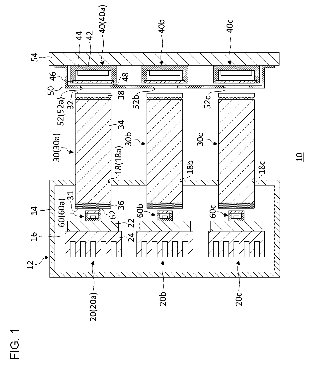
[0020]FIG. 1 schematically shows a configuration of a test device 10 according to the embodiment. The test device includes a constant-temperature device 12, a plurality of supports 20 (20a, 20b, 20c), a plurality of light guides 30 (30a, 30b, 30c), a plurality of light receiving devices 40 (40a, 40b, 40c), and a shield plate 50. The test device 10 is a device for performing a current-carrying test of a plurality of light emitting devices 60 (60a, 60b, 60c) collectively.

[0021]The light emitting device 60 tested is an ultra violet-light emitting diode (UV-LED) for outputting ...


PUM


Abstract

A test device includes: a support that supports a light emitting device subject to a test; a light waveguide that guides light output from the light emitting device supported by the support; a light diffuser plate that diffuses light output from the light waveguide; and a light receiving device that receives light diffused by the light diffuser plate. The test device may further include a constant-temperature device that houses the support and the light emitting device supported by the support and control a temperature of the light emitting device. The light receiving device may be provided outside the constant-temperature device, and the light waveguide may guide light from inside the constant-temperature device to a space outside the constant-temperature device.

Description

RELATED APPLICATION[0001]Priority is claimed to Japanese Patent Application No. 2016-200383, filed on Oct. 11, 2016, the entire content of which is incorporated herein by reference.BACKGROUND OF THE INVENTION1. Field of the Invention[0002]The present invention relates to test devices for light emitting devices.2. Description of the Related Art[0003]Light emitting devices such as LEDs are evaluated for reliability in a current-carrying test performed for a long period of time. The test device for performing a current-carrying test like this is exemplified by a test device capable of testing a semiconductor light emitting device in an environment of a temperature lower or higher than the room temperature, without mounting a light component carrying the semiconductor light emitting device on a substrate, etc.[0004]In the case of testing a light emitting device capable of outputting light such as deep ultraviolet light having a short wavelength and a high energy, the light receiving dev...

Claims


Application Information

Patent Timeline
IPC IPC(8): G01J3/02G01R31/26H01L33/00
CPCG01J3/0286G01R31/2635G01R31/2642H01L33/0095G01J3/0218G01J1/0214G01J1/0252G01J1/0271G01J1/0418G01J1/0425G01J1/0437G01J1/0474G01J2001/4252G01R31/26G01R31/2601G01R31/44
Inventor NIIZEKI, SHOICHIICHINOKURA, HIROYASU
Owner NIKKISO COMPANY
Why Eureka
Try Eureka