Panoramic sensing apparatus

a technology of panoramic sensing and spherical composite fresnel, which is applied in the direction of lighting and heating equipment, instruments, and power sources with built-in power, can solve the problems of relative small sensing distance, relative short sensing distance, and difficult to achieve a wide range of panoramic sensing, so as to improve precision and defect-free rate, reduce processing difficulty, and increase detection range

Inactive Publication Date: 2019-08-01
BOLYMEDIA HLDG
View PDF1 Cites 2 Cited by
  • Summary
  • Abstract
  • Description
  • Claims
  • Application Information

AI Technical Summary

Benefits of technology

[0007]According to the panoramic sensing apparatus of the present disclosure, a composite Fresnel lens in the shape of a frustum is used to realize the sensing of the boundary of the detection range, which is sufficient for most application scenarios where only the peripheral boundary needs to be detected. In the case where lens areas are the same as a whole, the composite Fresnel refracting surface arranged on the sidewall of the frustum only detects the boundary without having to take into account the internal points, so the sensing distance can be designed to be larger to obtain a larger detection range. Moreover, compared with the composite Fresnel refracting surface arranged on a spherical surface or a spherical polyhedron, the composite Fresnel refracting surface arranged on the sidewall of the frustum involves lowered processing difficulty, and accordingly improved precision and defect-free rate.

Problems solved by technology

It is very difficult to manufacture an original mold of the spherical composite Fresnel lens, especially when it is desired to arrange the tooth surface on the inner surface of the spherical surface.
On the other hand, due to the idea of interior point detection, the Fresnel units are covered densely on the surface of the spherical surface, so the area of a single Fresnel unit is relatively small, leading to a relative short sensing distance and a relative tiny coverage, which makes it difficult to achieve a wide range of panoramic sensing.

Method used


Image

  • Panoramic sensing apparatus
  • Panoramic sensing apparatus
  • Panoramic sensing apparatus

Examples


first embodiment

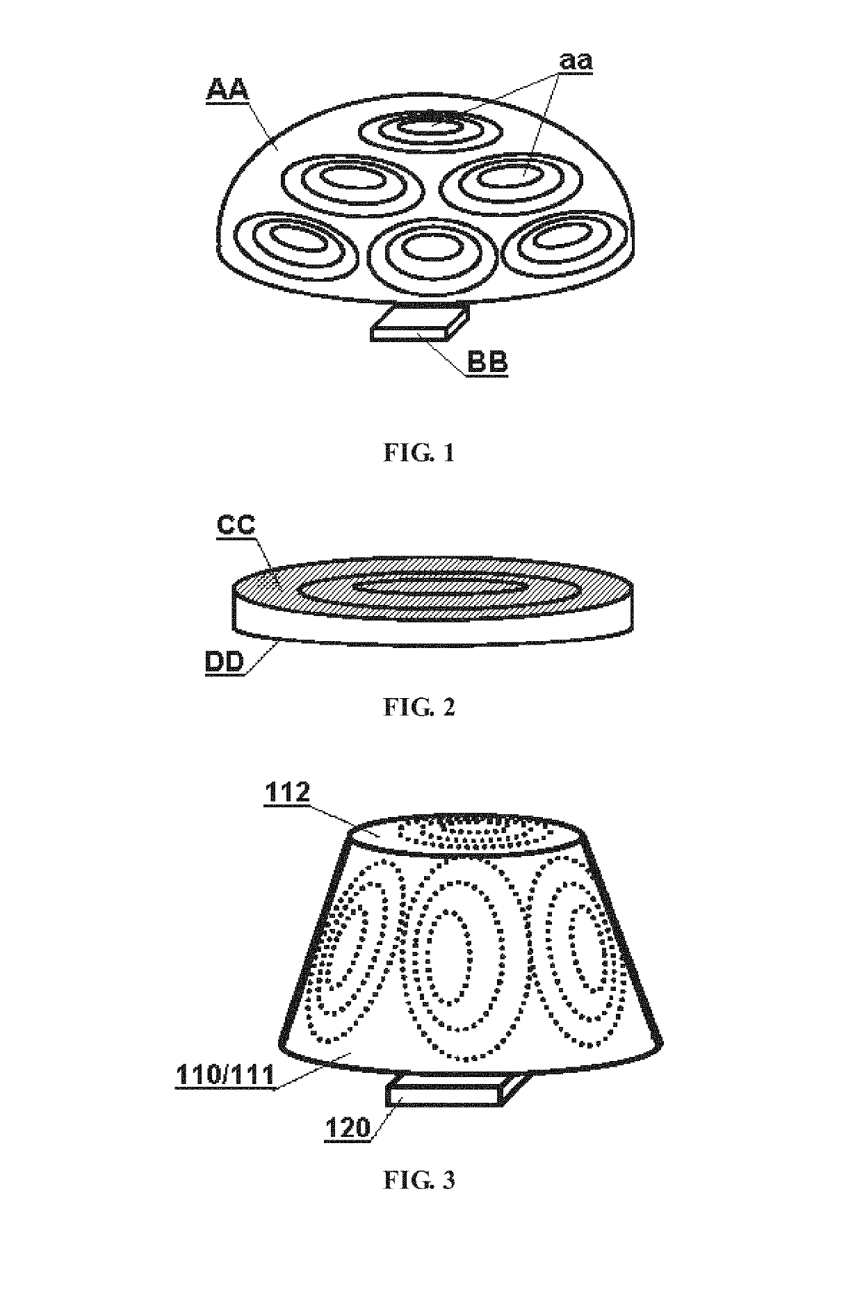
[0021]Referring to FIG. 3, a panoramic sensing apparatus according to the present disclosure may include a Fresnel lens system 110 and a light sensing device 120.

[0022]The Fresnel lens system 110 may include a composite Fresnel lens 111 shaped as a frustum, and the inner surface of a sidewall of the frustum is a tooth surface (indicated by a broken line in the figure) and the outer surface is smooth. In other embodiments, the tooth surface may also arranged on the outer surface of the frustum, or both the inner and outer surfaces of the frustum may be tooth surfaces.

[0023]The Fresnel lens system 110 may further include a top Fresnel lens 112 arranged on the top surface of the frustum. The “top surface” as used herein refers to an end having a smaller area, and the “bottom surface” refers to an end having a larger area. The top Fresnel lens has a planar circular shape which is in accordance with the shape of the top surface of the frustum. In this embodiment, the top Fresnel lens 112...

second embodiment

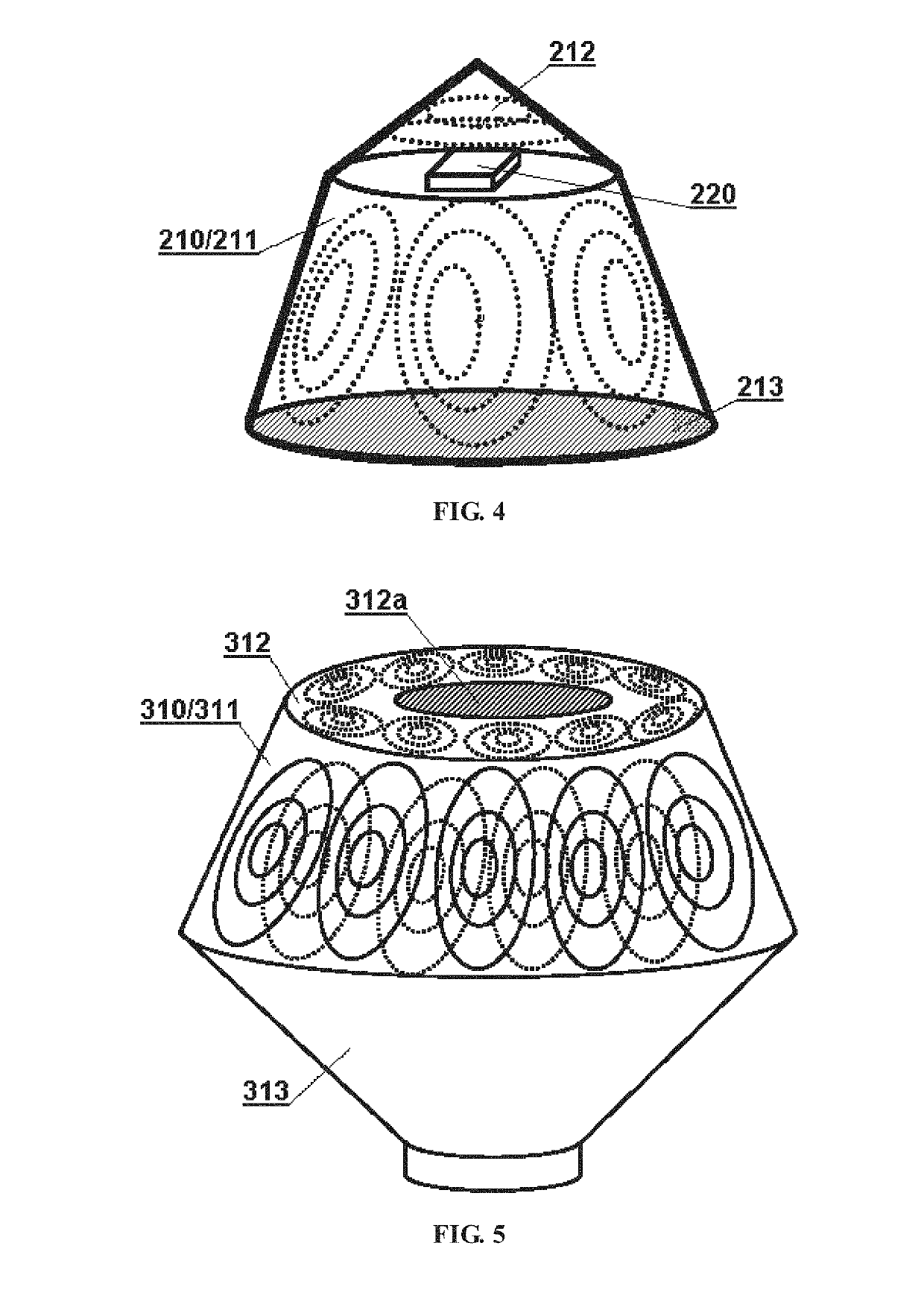
[0029]Referring to FIG. 4, a panoramic sensing apparatus according to the present disclosure may include a Fresnel lens system 210 and a light sensing device 220.

[0030]The Fresnel lens system 210 may include a composite Fresnel lens 211 shaped as a frustum, and the inner surface of a sidewall of the frustum is a tooth surface (indicated by a broken line in the figure) and the outer surface is smooth.

[0031]The Fresnel lens system 210 may further include a top Fresnel lens 212 arranged on the top surface of the frustum. The top Fresnel lens is shaped as a cone which has a bottom surface coincided with the top surface of the frustum. In this embodiment, the top Fresnel lens 212 is a single-sided simple Fresnel lens, of which the tooth surface is on the inner surface and is composed of a Fresnel unit which has a center coincided with the rotation axis of the frustum.

[0032]The Fresnel lens system 210 may further include a bottom reflector 213 arranged on the bottom surface of the frustum...

third embodiment

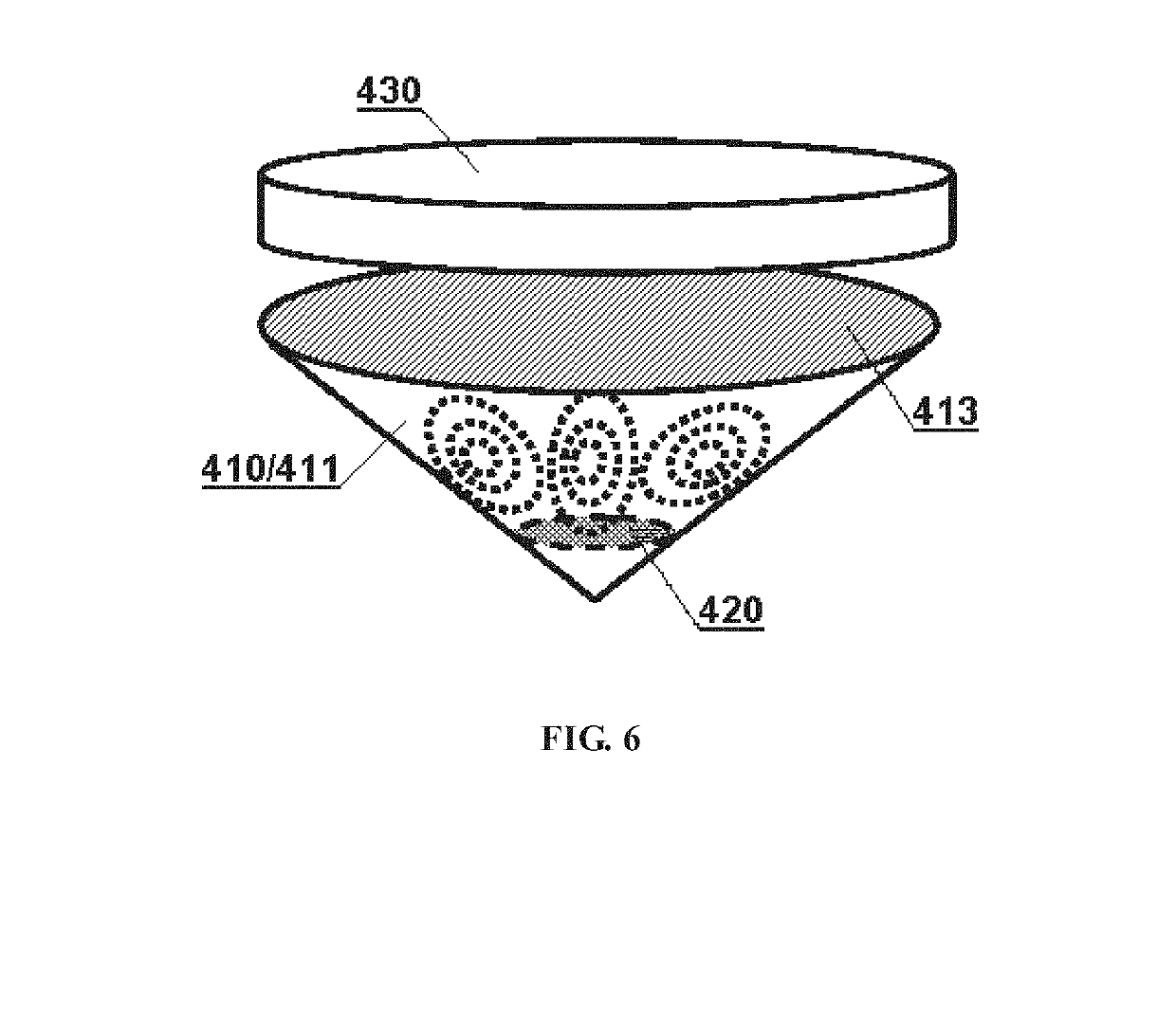
[0035]Referring to FIG. 5, a panoramic sensing apparatus according to the present disclosure may include a Fresnel lens system 310 and a light sensing device (not shown).

[0036]The Fresnel lens system 310 may include a composite Fresnel lens 311 shaped as a frustum, and both the inner surface and the outer surface of a sidewall of the frustum are tooth surfaces (in the figure, the Fresnel unit of the inner surface is indicated by a broken line, and the Fresnel unit of the outer surface is indicated by a solid line). The Fresnel units on each tooth surface are evenly arranged around the rotation axis of the frustum, and the numbers of the Fresnel units on the two tooth surfaces respectively are identical. In other embodiments, the numbers of the Fresnel units on the inner and outer tooth surfaces respectively may be different. As a preferred embodiment, in the present embodiment, the centers of the Fresnel units on the inner surface and the centers of the Fresnel units on the outer su...


PUM


Abstract

A panoramic sensing apparatus, comprising: a Fresnel lens system (110) and a light sensing device (120). The Fresnel lens system (110) comprises a composite Fresnel lens (111) in a shape of a frustum, at least one of an inner surface and an outer surface of a sidewall of the frustum being a tooth surface; at least two Fresnel units are distributed on said tooth surface. The light sensing device (120) is used for sensing light rays converged by the Fresnel lens system (110). As the composite Fresnel lens in the shape of a frustum is employed for sensing boundaries of a detection range, in the case where lens areas are the same as a whole, a larger detection range may be obtained, or light energy from each direction may be collected. Further, compared with a composite Fresnel refraction surface arranged on a spherical surface or on a spherical polyhedron, the composite Fresnel refraction surface which is arranged on a sidewall of a frustum involves lowered processing difficulty, and accordingly improved precision and defect-free rate.

Description

TECHNICAL FIELD[0001]The present disclosure relates to a technical field about panoramic sensing apparatus, more particularly to sensing apparatus which use Fresnel lenses for large field of view sensing and is suitable for panoramic or non-panoramic applications with large field of view.BACKGROUND OF THE INVENTION[0002]The technology of panoramic sensing has been used increasingly. With respect to the design idea of the panoramic sensing technology now available, it generally adopts “interior point detection”, that is, detecting each and every point within a sensing range comprehensively and the spectrum usually sensed mainly including infrared light arid visible light. Upon such detection idea, a condensing lens used is commonly designed as a spherical Fresnel lens.[0003]FIG. 1 shows a conventional panoramic sensing device which includes a spherical Fresnel lens AA and a light sensing device BB. The spherical Fresnel lens AA is a composite Fresnel lens having a tooth surface as it...

Claims


Application Information

Patent Timeline
Patent Type & Authority Applications(United States)
IPC IPC(8): G02B19/00G02B3/08H02S40/22
CPCG02B19/0076G02B3/08G02B19/0009H02S40/22F24S23/31F24S23/75F24S2023/86G02B3/0006G02B19/0014G02B19/0042G02B19/008G02B19/009H01L31/02325H01L31/0543Y02E10/52F21S9/03
Inventor HU, XIAOPING
Owner BOLYMEDIA HLDG
Why Eureka
Try Eureka