
Low temperature engine start method for smart battery

a smart battery, low temperature technology, applied in the field of smart battery systems, can solve the problems of improper operation and the space for improvement in actual use of traditional battery systems, and achieve the effect of high-power battery modules and high-power battery modules

Inactive Publication Date: 2019-08-01
LO KWUN HING
View PDF0 Cites 2 Cited by
  • Summary
  • Abstract
  • Description
  • Claims
  • Application Information

AI Technical Summary

Benefits of technology

The invention is a power supply system for starting an engine in a low temperature environment. The system includes a main battery module and a standby battery module. The main battery module has a higher temperature and higher stored power than the standby battery module. The standby battery module can provide power to start the engine when the main battery module is unable to do so. The system can enter a standby power supply mode to start the engine, and the user can control and set the system through a handheld control device. The standby battery module has a higher temperature and lower stored power than the high power battery module, so it can heat up the engine and start it. The system can provide power to start the engine even in a low temperature environment.

Problems solved by technology

The general battery system is used to start the engine, so as to start the vehicle, ship or mechanical equipment connected with the battery system, and to assist in providing the power to the device connected with the power supply circuit; however, the traditional battery system can not be properly operated in the low temperature environment, and the standby power supply circuit is not disposed to provide the power for starting the engine immediately when the main battery of the system is exhausted; therefore, the traditional battery system still has a lot of space for improvement in actual use.

Method used


Image

  • Low temperature engine start method for smart battery
  • Low temperature engine start method for smart battery
  • Low temperature engine start method for smart battery

Examples


Embodiment Construction

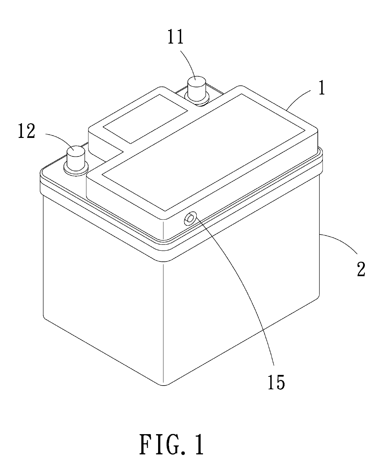
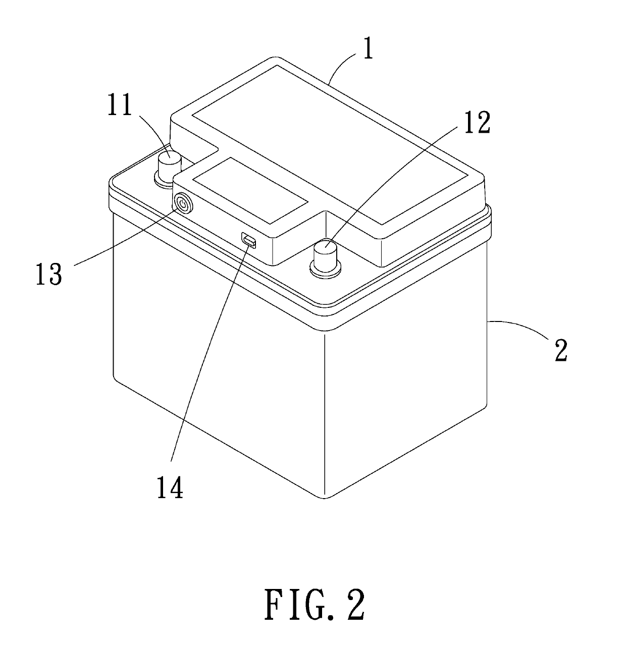
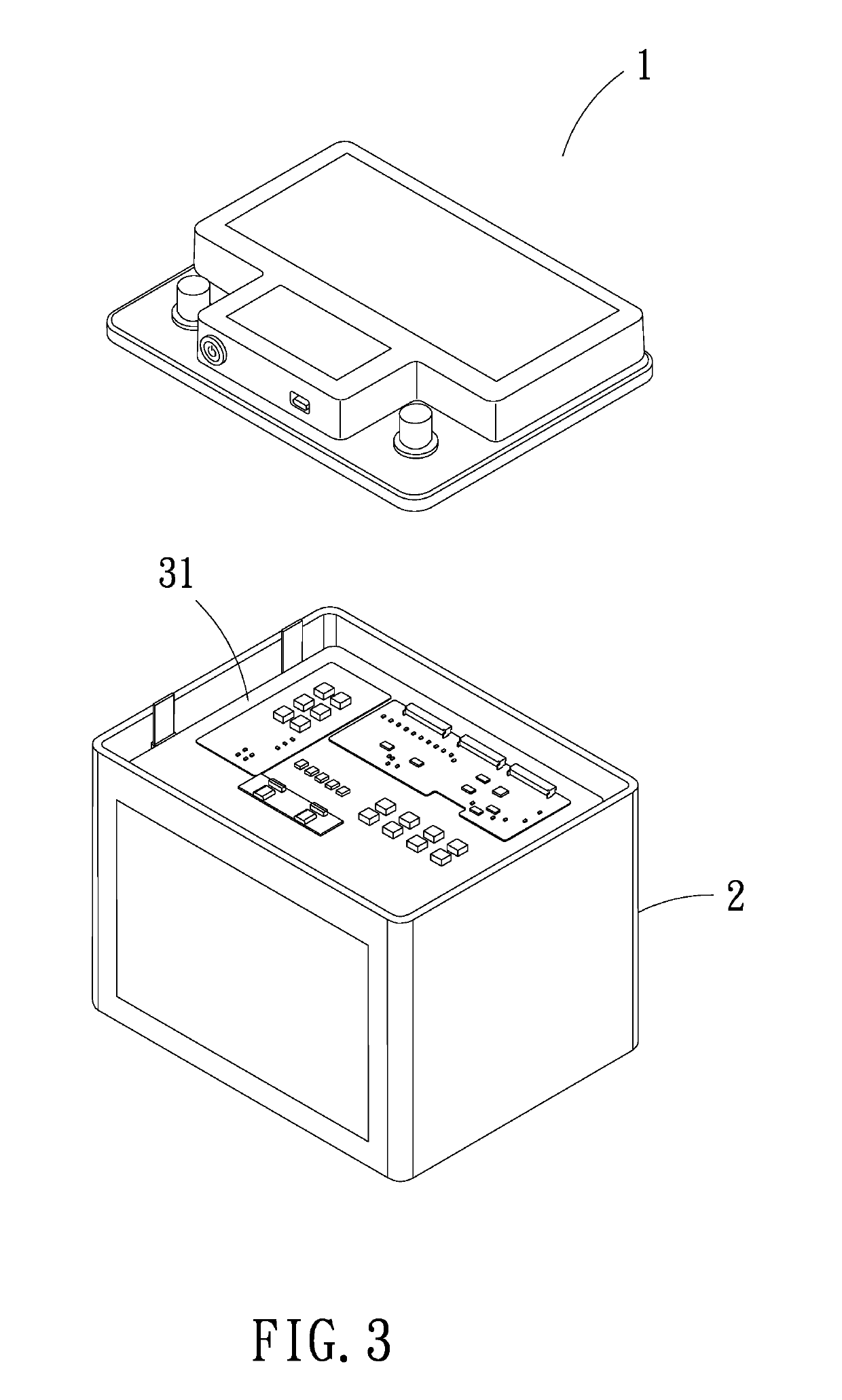
[0014]Embodiment 1, please refer to FIG. 1 to FIG. 9, a smart battery system of the invention that can be used for starting the engine in the low temperature, comprises upper cover 1, outer casing 2, body and handheld control device; the handheld control device is provided with wireless transmission module; the body is disposed inside the outer casing 2, and the upper cover 1 is disposed above the outer casing 2. The upper cover 1 is provided with a positive connection terminal 11, a negative connection terminal 12, a start switch 13, a data port 14 and a DC voltage input port 15. The body includes system base plate 31, main battery module, high power battery module, low temperature battery module and a plurality of heating plates 35; the system base plate 31 is provided with a wireless transmission module; wherein, the heating plate 35 is disposed around the high power battery module and the low temperature battery module, and the outside of the heating plate 35 is cover-provided w...


PUM


Abstract

A power supply method of starting an engine in a low temperature environment for a smart battery system including an outer casing, an upper cover disposed above the outer casing, and a body disposed inside the outer casing. The method includes the temperature of the main battery module of the smart battery system is within the system default operating temperature range of the system battery, the stored power of the main battery module is higher than the default power storage value of the main battery used to start the engine, the user can directly operate or control the start power switch of the vehicle, the ship or the mechanical equipment, and the main battery module of the smart battery system can provide the power output to the power supply circuit of the battery system connected with the vehicle, ship or mechanical equipment, so as to start the engine.

Description

BACKGROUND OF THE INVENTION1. Field of the Invention[0001]The invention relates to smart battery systems and more particularly to a power supply method of starting an engine in a low temperature environment for a smart battery system.2. Description of Related Art[0002]The general battery system is used to start the engine, so as to start the vehicle, ship or mechanical equipment connected with the battery system, and to assist in providing the power to the device connected with the power supply circuit; however, the traditional battery system can not be properly operated in the low temperature environment, and the standby power supply circuit is not disposed to provide the power for starting the engine immediately when the main battery of the system is exhausted; therefore, the traditional battery system still has a lot of space for improvement in actual use.SUMMARY OF THE INVENTION[0003]It is therefore one object of the invention to provide a power supply method of starting an engi...

Claims


Application Information

Patent Timeline
IPC IPC(8): H01M10/42H01M10/6555H01M2/10H01M10/615H01M10/625H01M10/44H02J7/00F02N11/08H01M50/249H01M50/271
CPCH02J7/0063H02J7/007F02N11/0862H01M2220/20H01M10/4257H01M10/6555H01M2/1077H01M10/615H01M10/625H01M10/44H01M10/443H01M10/6554F02N2200/064F02N2200/061Y02E60/10H01M50/249H01M50/271
Inventor LO, KWUN HING
Owner LO KWUN HING
Learn More