Shape memory alloy crimp interlock apparatus and methods

a technology of memory alloy and interlocking device, which is applied in the direction of shape memory alloy connection, line/current collector details, and permanent deformation connections, etc., can solve the problems of reducing the tensile strength or recovery properties of the filament, affecting the effect of crimping, and affecting the mechanical properties of the filament in a deleterious fashion

Active Publication Date: 2019-08-08
AUTOSPLICE SYST
View PDF0 Cites 4 Cited by
  • Summary
  • Abstract
  • Description
  • Claims
  • Application Information

AI Technical Summary

Benefits of technology

[0011]In addition, improved apparatus and methods for the manufacture and packaging of SMA wire assemblies are also needed in order to maintain these precision assemblies cost-effective and competitive from a manufacturing perspective. Such improved manufacture and packaging approaches would also ideally be compatible with extant industry-standard equipment and techniques to the maximum degree practicable, thereby minimizing the degree of infrastructure and equipment alterations and upgrades necessary to implement the technology.DETAILED DESCRIPTION

Problems solved by technology

Despite the broad range of crimp technologies and implementations of SMA filaments, there has heretofore been significant difficulty in effectively crimping SMA filament wire when finer wire gauge sizes are chosen.
Specifically, prior art approaches to crimping such filaments (including use of serrations or “teeth” in the crimp surfaces) either significantly distort or damage the filament, thereby altering its mechanical characteristics in a deleterious fashion (e.g., reducing its tensile strength or recovery properties), or allowing it to slip or move within the crimp.
These problems are often exacerbated by changes in the environment (e.g., temperature, stress, etc.) of the SMA filament and crimp.
Other techniques such as brazing, soldering, and the like are also not suitable for such fine-gauge applications.
Furthermore, no suitable solution exists for maintaining a constant and uniform tensile stress on the filament during crimping.
There is, therefore, a salient unsatisfied need for an improved crimp apparatus and methods of manufacture that specifically accommodate finer gauge SMA filament wire assemblies, especially so as to maintain the desired degree of filament length control post-crimp for, inter alia, length-critical actuator applications.

Method used


Image

  • Shape memory alloy crimp interlock apparatus and methods
  • Shape memory alloy crimp interlock apparatus and methods
  • Shape memory alloy crimp interlock apparatus and methods

Examples


Embodiment Construction

[0012]Reference is now made to the drawings wherein like numerals refer to like parts throughout.

BRIEF DESCRIPTION OF THE DRAWINGS

[0013]The features, objectives, and advantages of the invention will become more apparent from the detailed description set forth below when taken in conjunction with the drawings, wherein:

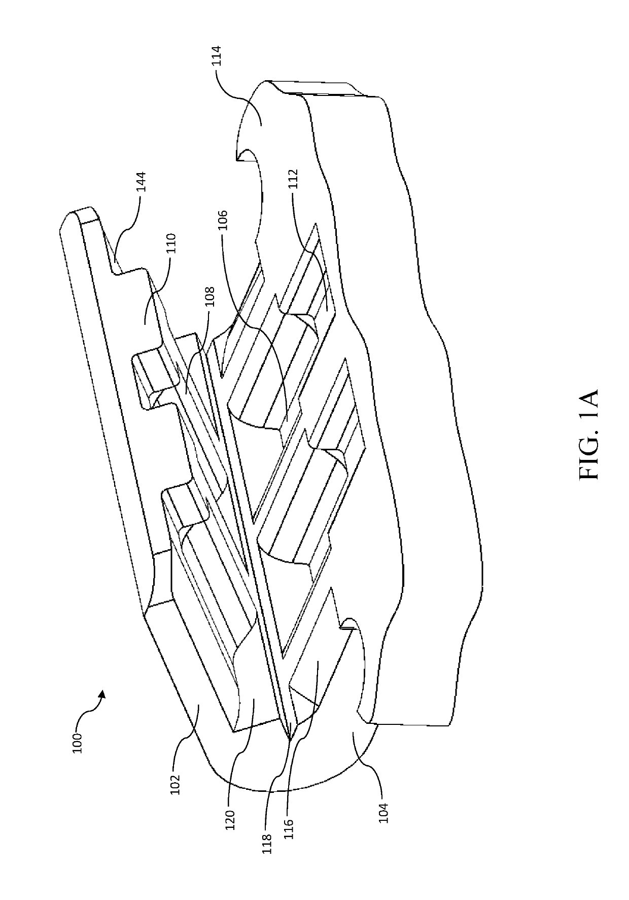
[0014]FIG. 1A is a perspective view of an exemplary shape memory alloy interlock assembly prior to crimping, in accordance with the principles of the present disclosure.

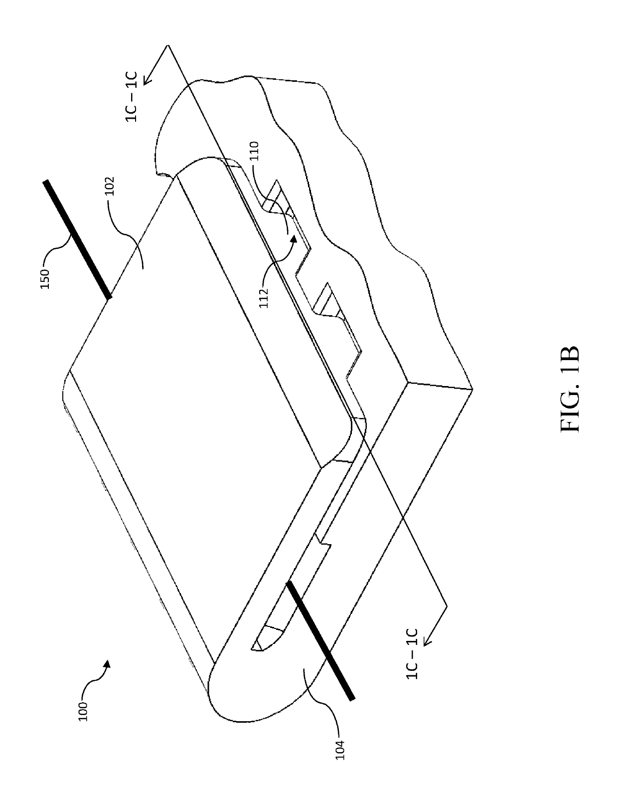
[0015]FIG. 1B is a perspective view of the shape memory alloy interlock assembly of FIG. 1A showing a shape memory alloy filament crimped therein, in accordance with the principles of the present disclosure.

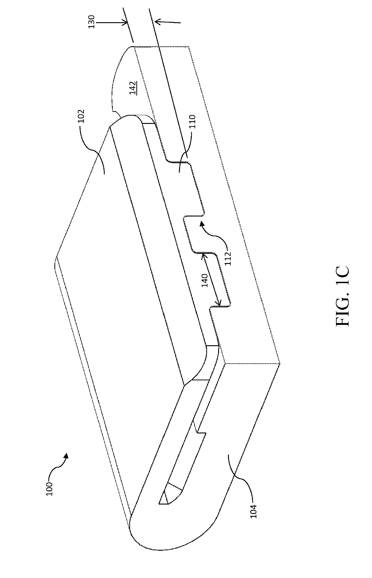
[0016]FIG. 1C is a cross sectional view of the shape memory alloy interlock assembly of FIG. 1A, in accordance with the principles of the present disclosure.

[0017]FIG. 2 is a perspective view of another exemplary shape memory alloy interlock assembly prior to crimping, in accordance with the principle...


PUM


Abstract

Apparatus and methods for filament crimping. In one embodiment, the apparatus comprises a body and a filament crimp element. The filament crimp element comprises a first set of cavities disposed at a spacing which creates a first set of features and a second set of cavities disposed at a spacing which creates a second set of features. The first and second set cavities are substantially opposite one another. The first set of features are adapted to be placed at least partially within the second set of cavities and the second set of features are adapted to be placed at least partially within the first set of cavities. Interlock features configured for cold welding are also included. Methods and apparatus for the manufacture of the device are also disclosed. In addition, methods for automated placement and manufacture of assemblies using the crimp elements are also disclosed.

Description

PRIORITY[0001]This application claims the benefit of priority to co-owned and co-pending U.S. Provisional Patent Application Ser. No. 62 / 627,539 filed on Feb. 7, 2018 and entitled “Shape Memory Alloy Crimp Interlock Apparatus and Methods”, the contents of which being incorporated herein by reference in its entirety.RELATED APPLICATIONS[0002]This application is related to co-owned U.S. patent application Ser. No. 13 / 372,199 filed on Feb. 13, 2012 and entitled “Apparatus and Methods for Filament Crimping and Manufacturing”, now U.S. Pat. No. 8,939,180; which is a divisional of and claims priority to co-owned U.S. patent application Ser. No. 12 / 892,208 filed Jul. 1, 2010 of the same title, now U.S. Pat. No. 8,113,243; which is a divisional of and claims priority to co-owned U.S. patent application Ser. No. 12 / 691,562 filed Jan. 21, 2010 of the same title, now U.S. Pat. No. 7,926,520, which is a divisional of and claims priority to co-owned U.S. patent application Ser. No. 11 / 473,567 fi...

Claims


Application Information

Patent Timeline
Patent Type & Authority Applications(United States)
IPC IPC(8): F03G7/06H01R43/048H01R4/18H01R4/01
CPCF03G7/065H01R43/048H01R4/18H01R4/01H01R4/188F03G7/06F03G7/0614F03G7/0645
Inventor FOSHANSKY, LEONIDNAIDU, VISHNUKRONE, KENNETH
Owner AUTOSPLICE SYST
Why Eureka
Try Eureka