Controlling execution of a block of program instructions within a computer processing system

a computer processing system and program instruction technology, applied in the field of data processing systems, can solve problems such as adverse effects on overall performan

Inactive Publication Date: 2005-11-17
ARM LTD
View PDF7 Cites 11 Cited by
  • Summary
  • Abstract
  • Description
  • Claims
  • Application Information

AI Technical Summary

Benefits of technology

[0011] The present technique recognises that for a large number of blocks of program instructions that can advantageously be the subject of calls from different points within a program, the return instruction represents a significant overhead. Combined with this is the realisation that such small blocks of program instructions rarely need to include therein branch instructions such that when they are started they will with a high degree of probability always be run to their conclusion, i.e. result in a fixed number of program instructions being fetched and executed. Accordingly, the execute block instruction provided by the present technique specifies within the execute block instruction both the location of the block of program instructions to be executed as well as the length of that block of program instructions. Accordingly, there is no need for the block of program instructions to include a return instruction, since the length of the block is already known as specified within the execute block instruction and the return to the main program can be triggered when the final instruction within the block of program instructions has been executed. This execute block instruction extends the advantages of program instruction calls to small blocks of program instructions. The technique is also particularly well suited to use by program compilers which can identify frequently occurring small blocks of instructions within a program image and replace these by execute block instructions. The occurrence of a block in the normal code can be used as the target of branch instructions without the need to separately store the block of instructions elsewhere.
[0013] Accordingly, execute block instruction logic is provided which stores an indication of a memory location of an instruction following the execute block instruction. The execute block instruction logic determines when the last instruction in the block of two or more program instructions is being processed. When it is determined that the last instruction in the block of two or more program instructions is being processed then an indication of the memory location of an instruction following the execute block instruction is provided to the instruction fetching circuit. Providing the indication of the memory location of the instruction following the execute block instruction to the instruction fetching circuit causes the fetch unit to fetch that instruction. It will be appreciated that in some fetch units which take multiple cycles to fetch instructions or where the fetch unit fetches blocks of instructions, one or more instructions linearly following the last instruction may still be fetched by the fetch unit but these instructions will not be executed. In this way, the correct sequence of instructions is fetched by the fetch unit which avoids the need to flush instructions, with all the attendant performance implications which result from such flushing. Hence, it will be appreciated that the provision of the execute block logic enables the execute block instruction to be implemented in an efficient manner whilst minimising the degree of any architectural changes which may be required.
[0015] Accordingly, execute block instruction logic is provided which stores an indication of a memory location of an instruction pointed to by the location field within the execute block instruction. The execute block instruction logic determines when the execute block instruction is being processed. When it is determined that the execute block instruction is being processed then an indication of the memory location of the instruction referred to by the execute block instruction is provided to the instruction fetching circuit. Providing the indication of the memory location of the instruction referenced to the execute block instruction to the instruction fetching circuit causes the fetch unit to fetch that instruction. As mentioned previously, in fetch units which take multiple cycles to fetch instructions or where the fetch unit fetches blocks of instructions, one or more instructions sequentially following the execute block instruction may still be fetched by the fetch unit but these instructions will not be executed. In this way, the correct sequence of instructions is fetched by the fetch unit which avoids the need to flush instructions, with all the attendant performance implications which result from such flushing.
[0028] In embodiments, the interrupt handling logic prevents the pushing of the indication of the memory location of the instruction following the execute block instruction onto the return stack in response to the execute block instruction being processed following the interrupt.
[0029] Preventing the pushing the indication of the memory location of the instruction following the execute block instruction onto the return stack following completion of the handling of the interrupt prevents duplication (of the entry corresponding to the EMB instruction) on the return stack which would otherwise occur and result in non-optimal operation.
[0033] Accordingly, when reusing existing hardware which prevents non-branch instructions from causing the prediction logic determining whether a target memory address is associated therewith, prediction prevention override logic is provided which overrides this restriction on when the last instruction in the block is being processed which enables this instruction to be treated in a manner analogous to a branch instruction despite there being no decoded control signals would be associated with that instruction to indicate this.

Problems solved by technology

However, it will be appreciated that the last instruction itself would not typically provide an indication of the memory location of the instruction following execute block instruction or contain any information which would normally enable such an indication to be provided.
Also, because the last instruction is typically not an instruction which would normally be interpreted as being encoded as a branch, the likelihood that executing that instruction will result in a branch would not normally ever be considered as a possibility and, hence, the fetch unit would typically assume that it is required to linearly access instructions following the last instruction.
Accordingly, the number of flushes that would need to be performed would also be relatively high, which may have an adverse effect on overall performance.

Method used


Image

  • Controlling execution of a block of program instructions within a computer processing system
  • Controlling execution of a block of program instructions within a computer processing system
  • Controlling execution of a block of program instructions within a computer processing system

Examples


Embodiment Construction

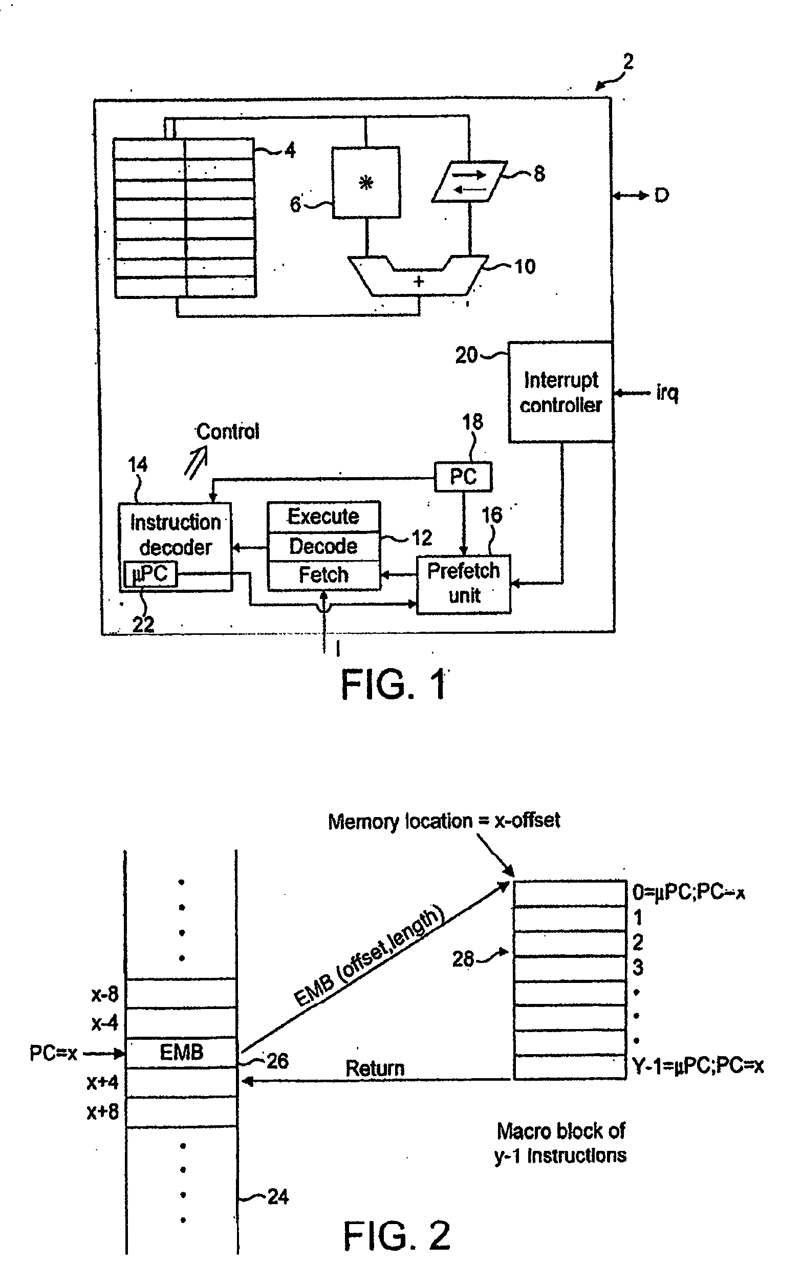
[0051]FIG. 1 shows a data processing apparatus 2 including a register bank 4, a multiplier 6, a shifter 8, an adder 10, an instruction pipeline 12, an instruction decoder 14, a prefetch unit 16, a program counter register 18 and an interrupt controller 20. It will be appreciated that the data processing apparatus 2 as illustrated in FIG. 1 will typically include many further circuit elements, but these have been omitted for the sake of clarity. In operation, instructions are fetched from a memory under control of the prefetch unit 16 and a memory location as specified in the program counter register 18 into the fetch stage of the instruction pipeline 12. The instructions progress along the instruction pipeline 12 to a decode stage and then to an execute stage in accordance with normal microprocessing techniques. The instruction decoder 14 decodes the program instructions in the decode stage and generates control signals which are used to configure the circuit elements, such as the r...


PUM


Abstract

A data processing apparatus and method are disclosed. The data processing apparatus comprises: an instruction fetching circuit operable to fetch a sequence of program instructions from a sequence of memory locations; an instruction decoder responsive to program instructions within the sequence of program instructions fetched by the instruction fetching circuit to control data processing operations specified by the program instructions; and an execution circuit operable under control of the instruction decoder to execute the data processing operations, wherein the instruction decoder is responsive to an execute block instruction within the sequence of program instructions to trigger fetching of a block of two or more program instructions by the instruction fetching circuit and execution of the block of two or more program instructions by the execution circuit, the block of two or more instructions containing a number of program instructions specified by a block length field within the executed block instruction and being stored at a memory location specified by a location field within the execute block instruction, the apparatus further comprises execute block instruction logic operable in response to the execute block instruction to store an indication of a memory location of an instruction following the execute block instruction and to determine which instruction in the block of two or more program instructions is being processed, the execute block instruction logic being further operable when it is determined that a last instruction in the block of two or more program instructions is being processed to provide to the instruction fetching circuit the indication of the memory location of the instruction following the execute block instruction so that the instruction following the execute block instruction is fetched for execution immediately following the last instruction in the block of two or more program instructions. Providing the indication of the memory location of the instruction following the execute block instruction to the instruction fetching circuit causes the fetch unit to fetch that instruction so that the correct sequence of instructions is fetched by the fetch unit which avoids the need to flush instructions.

Description

BACKGROUND OF THE INVENTION [0001] 1. Field of the Invention [0002] The present invention relates to the field of data processing systems. More particularly, the present invention relates to the control of execution of a block of program instructions within a data processing system. [0003] 2. Description of the Prior Art [0004] It is known that computer programs often contain sequences of program instructions that are frequently repeated within the computer program. In order to produce a computer program with a smaller code size, it is known to arrange such blocks of computer program instructions into functions or subroutines which can be called from various positions within the computer program. [0005] It is normal for such subroutines to terminate with a return instruction which commands the data processing system to return to the instruction immediately following the point in the computer program from where the call to the subroutine was made. When the subroutine or block of inst...

Claims


Application Information

Patent Timeline
Patent Type & Authority Applications(United States)
IPC IPC(8): G06F9/32
CPCG06F9/30054G06F9/3802G06F9/324G06F9/3836G06F9/3858G06F9/322
Inventor ELWOOD, MATTHEW PAULVASEKIN, VLADIMIR
Owner ARM LTD
Why Eureka
Try Eureka