Plasma jet spark plug and ignition system for the same

a technology of plasma jet and spark plug, which is applied in the direction of spark plugs, machines/engines, mechanical equipment, etc., can solve the problems of excessive fuel consumption, accidental firing due to unstable combustion, and significant wear of the electrode of the spark plug, so as to reduce the consumption of energy resources, improve the durability of the electrode of the plasma jet spark plug, and improve the fuel consumption

Inactive Publication Date: 2007-05-24
NGK SPARK PLUG CO LTD
View PDF6 Cites 13 Cited by
  • Summary
  • Abstract
  • Description
  • Claims
  • Application Information

AI Technical Summary

Benefits of technology

[0011] Since a plasma jet spark plug according to the first aspect of the invention has a construction such that one end of the ground electrode is bent towards a front end portion of the insulator in which a cavity is included so that plasma may be formed and shot out from an opening portion, a spark may be discharged outside the cavity in a spark discharge gap formed between the ground electrode and a center electrode. That is, since the air-fuel mixture in a combustion chamber can be ignited not only inside the cavity but also outside the cavity, ignitability may be improved compared to the case where the ignition is performed inside the cavity, despite the fact that the ignition is caused by only the spark discharge without plasma. Therefore, in the situation where high ignitability is required, such as while starting an internal combustion engine or while idling, the ignition can be performed by shooting out plasma. On the other hand, in the situation where high ignitability is not required, such as during high speed running of an internal combustion engine, the ignition can be performed by only the spark discharge.
[0012] The high energy of a plasma is likely to cause significant overheating and wearing out of an electrode of a plasma jet spark plug. However, when an ignition method is properly used according to the operational status, i.e., low or high speed operation, of an internal combustion engine as mentioned above, the degree of electrode consumption may be minimized, thereby resulting in improved durability of the plasma jet spark plug. Further, because the number of times it is necessary to utilize high energy for forming plasma is reduced, it leads to less consumption of energy resources, such as a battery and an improvement of fuel consumption.
[0013] When a spark discharge gap comprises an aerial discharge gap, an outer creeping discharge gap and an inner creeping discharge gap according to the second aspect of the invention, effective ignition of an air-fuel mixture may be achieved by the spark discharged in the aerial discharge gap and the outer creeping discharge gap without forming plasma. Further, despite the fact that a plasma jet spark plug is fouled, the plasma jet spark plug of the present invention can clean the surface of the front end portion of the insulator because high energy plasma may shoot out.
[0015] Further, with an ignition system according to the fourth aspect of the invention, the plasma jet spark plug according to any one of aspects one through three of the invention can be properly and effectively used according to the operational status of the internal combustion engines. Therefore, the durability of the electrode of a plasma jet spark plug may be improved. Furthermore, it is possible to reduce the consumption of energy resources, such as a battery and improve the fuel consumption.

Problems solved by technology

Conventionally, when an internal combustion engine such as automobile engine runs at low load (hereinafter referred to as “low load operation”), such as while starting or during idling, accidental firing due to unstable combustion tends to occur.
However, such an adjustment causes excessive fuel consumption.
However, plasma tends to cause an increase in temperature of a spark plug due to its high energy, thereby resulting in a significant wearing of the electrode of the spark plug.
Thus, poor ignitability and slow combustion may occur because a flame core cannot be formed in a flow of the air-fuel mixture in a combustion chamber.

Method used


Image

  • Plasma jet spark plug and ignition system for the same
  • Plasma jet spark plug and ignition system for the same
  • Plasma jet spark plug and ignition system for the same

Examples


Embodiment Construction

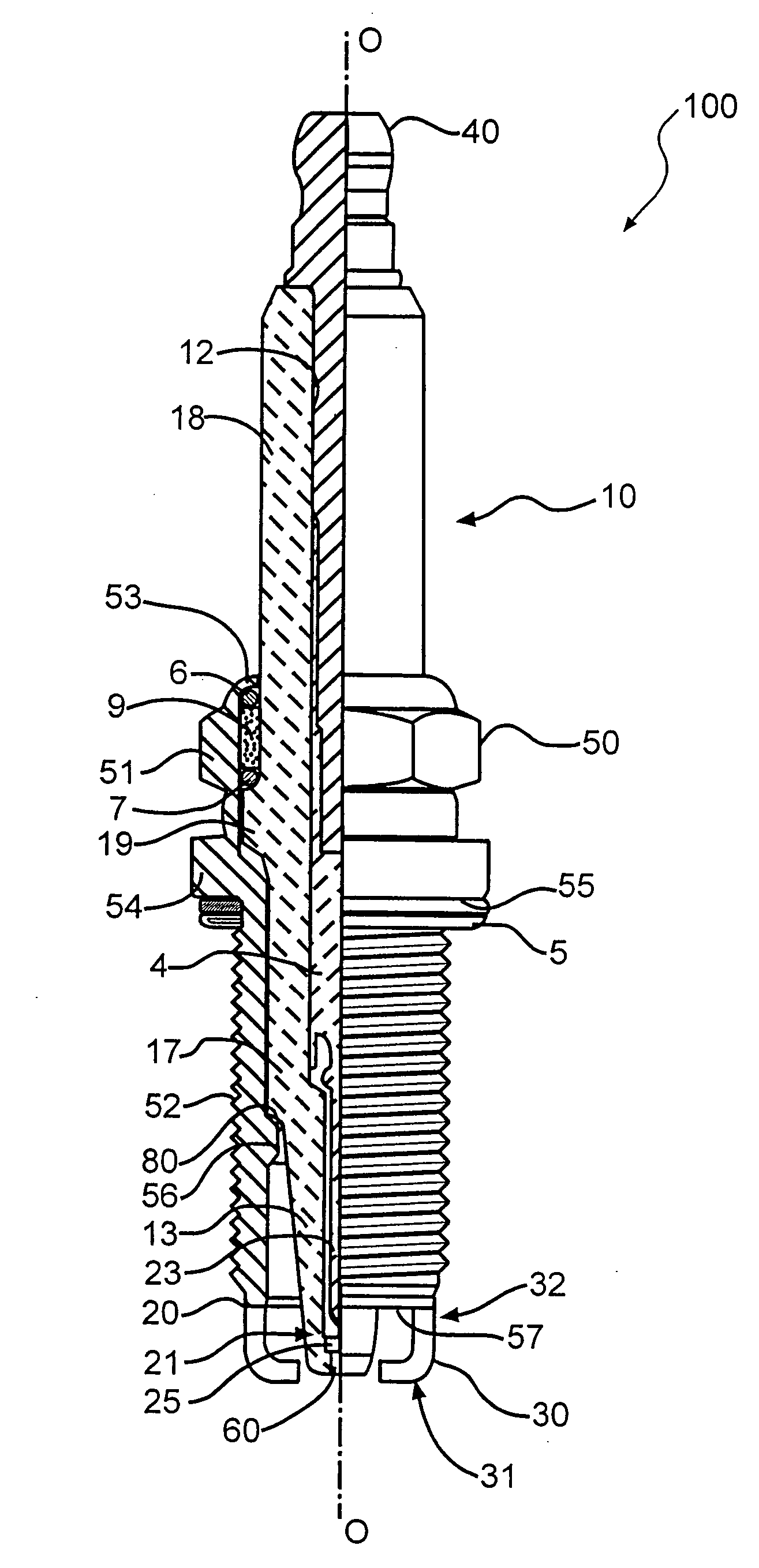
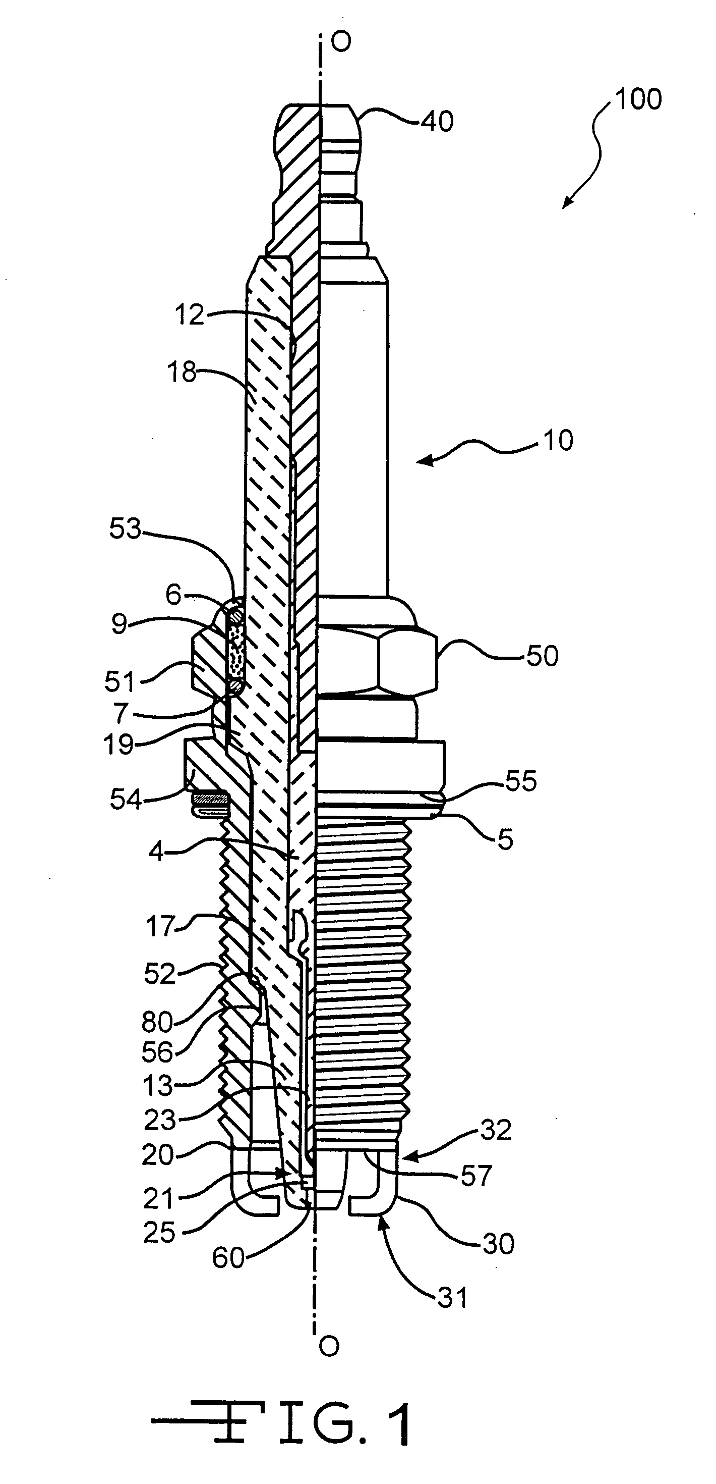
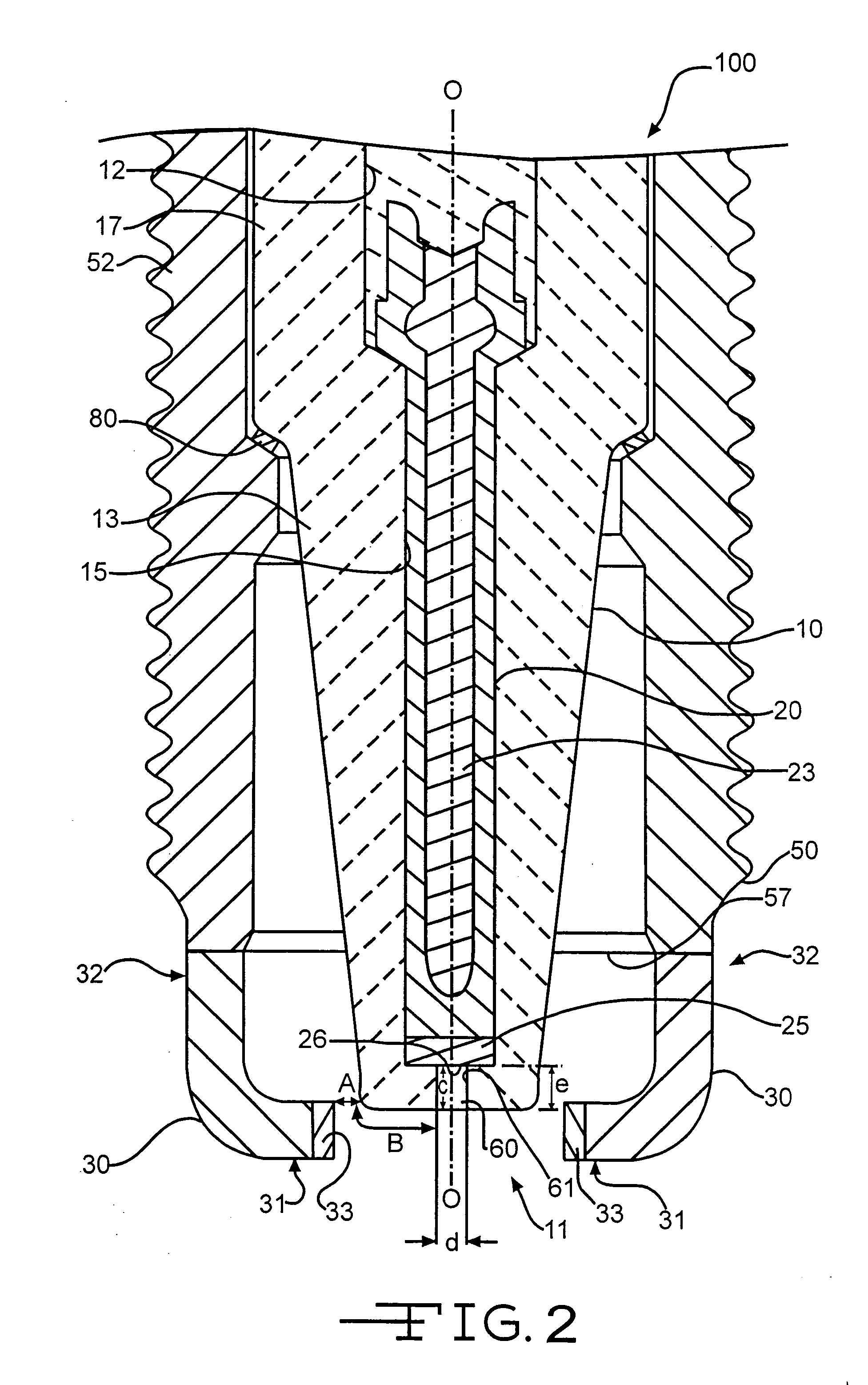
[0019] An embodiment of a plasma jet spark plug embodying the present invention and an ignition system for the plasma jet spark plug will now be described with reference to the drawings. First, referring to FIGS. 1 and 2, a construction of a plasma jet spark plug 100 according to the present invention will be explained. In FIG. 1, the direction of axis “O” of the plasma jet spark plug 100 is regarded as the top-to-bottom direction in the drawing. A lower portion of the drawing is regarded as a front end of the plasma jet spark plug 100 and an upper portion of the drawing is regarded as a back end of the plasma jet spark plug 100.

[0020] As shown in FIG. 1, the plasma jet spark plug 100 includes an insulator 10, a metal shell 50 holding the insulator 10 therein, a center electrode 20 held in the insulator 10 in the direction of the axis “O”, two pieces of ground electrode 30 each having a base portion 32 welded to a front end face 57 of the metal shell 50, wherein a front end portion...


PUM


Abstract

A plasma jet spark plug provides improved ignitability and durability by forming a part of a spark discharge gap outside the electric discharge space which generates plasma. An ignition system for the plasma jet spark plug is also disclosed. The plasma jet spark plug includes a center electrode, an insulator defining an axial bore which partially surrounds the center electrode, a cavity surrounded by an inner circumferential face of the axial bore which extends from an opening portion of a front end of the axial bore of the insulator and wherein a front end face of the center electrode is formed. A ground electrode is bent towards a front end portion of the insulator.

Description

BACKGROUND OF THE INVENTION [0001] The present invention relates to a plasma jet spark plug for an internal combustion engine which generates plasma to ignite an air-fuel mixture and to an ignition system for the plasma jet spark plug. [0002] Conventionally, when an internal combustion engine such as automobile engine runs at low load (hereinafter referred to as “low load operation”), such as while starting or during idling, accidental firing due to unstable combustion tends to occur. In response, lowering the mixture ratio of air and fuel (hereinafter referred to as “the A / F ratio”) is performed to facilitate smooth ignition and prevent stalling. However, such an adjustment causes excessive fuel consumption. Therefore, improvement in the ignition characteristics of a spark plug, which achieves secure ignition and a stable combustion of the air-fuel mixture despite a high A / F ratio has been demanded. [0003] A plasma jet spark plug is known as a spark plug with high ignitability as d...

Claims


Application Information

Patent Timeline
Patent Type & Authority Applications(United States)
IPC IPC(8): H01T13/20
CPCF02P3/0884F02P9/007H01T13/20H01T13/50
Inventor NAGASAWA, SATOSHIHAGIWARA, KATSUNORIMATSUTANI, WATARU
Owner NGK SPARK PLUG CO LTD
Why Eureka
Try Eureka