Low profile vehicle restraint

a vehicle restraint and low-profile technology, applied in domestic applications, loading/unloading, storage devices, etc., can solve the problems of not allowing the restraint, disengagement, and icc of the vehicle, and the loading dock area and the rear end of the trailer can be very harsh environments, so as to minimize the degree and extend the operating range

Inactive Publication Date: 2001-11-27
UNITED DOMINION INDS
View PDF4 Cites 11 Cited by
  • Summary
  • Abstract
  • Description
  • Claims
  • Application Information

AI Technical Summary

Benefits of technology

This invention, in a first preferred embodiment is directed to a low profile vehicle restraint. This invention employs the essential linkage of previous designs to enable the restraining hook to move in a vertical direction thus minimizing the degree to which the vehicle may move away from the loading dock. This embodiment however represents a departure by not fixing the geometry of the linkage so that the operating range may be extended.

Problems solved by technology

Prior systems due to mechanical configuration cannot operate within an envelop from 10 to 30 inches.
This will not allow them to engage, restrain and disengage a vehicle ICC within the totality of the contemporary operating envelop.
While such systems generally function well, and provide useful information to the control system, there are two major deficiencies in all of the previous systems.
First, the loading dock area and the rear end of trailers can be very harsh environment as a result of rain, snow, ice, road salt and other materials present at a loading dock.
These devices use mechanical limit switches which have moving parts which can become corroded or made inoperative by ice, dirt or other debris.
Even if the limit switch is an inductive proximity switch, it is still activated by the motion of a mechanical component of the restraining device, and are therefore is subject to malfunction or false signal if one of the moving components should become broken or stick from corrosion or other foreign matter.

Method used


Image

  • Low profile vehicle restraint
  • Low profile vehicle restraint
  • Low profile vehicle restraint

Examples


Embodiment Construction

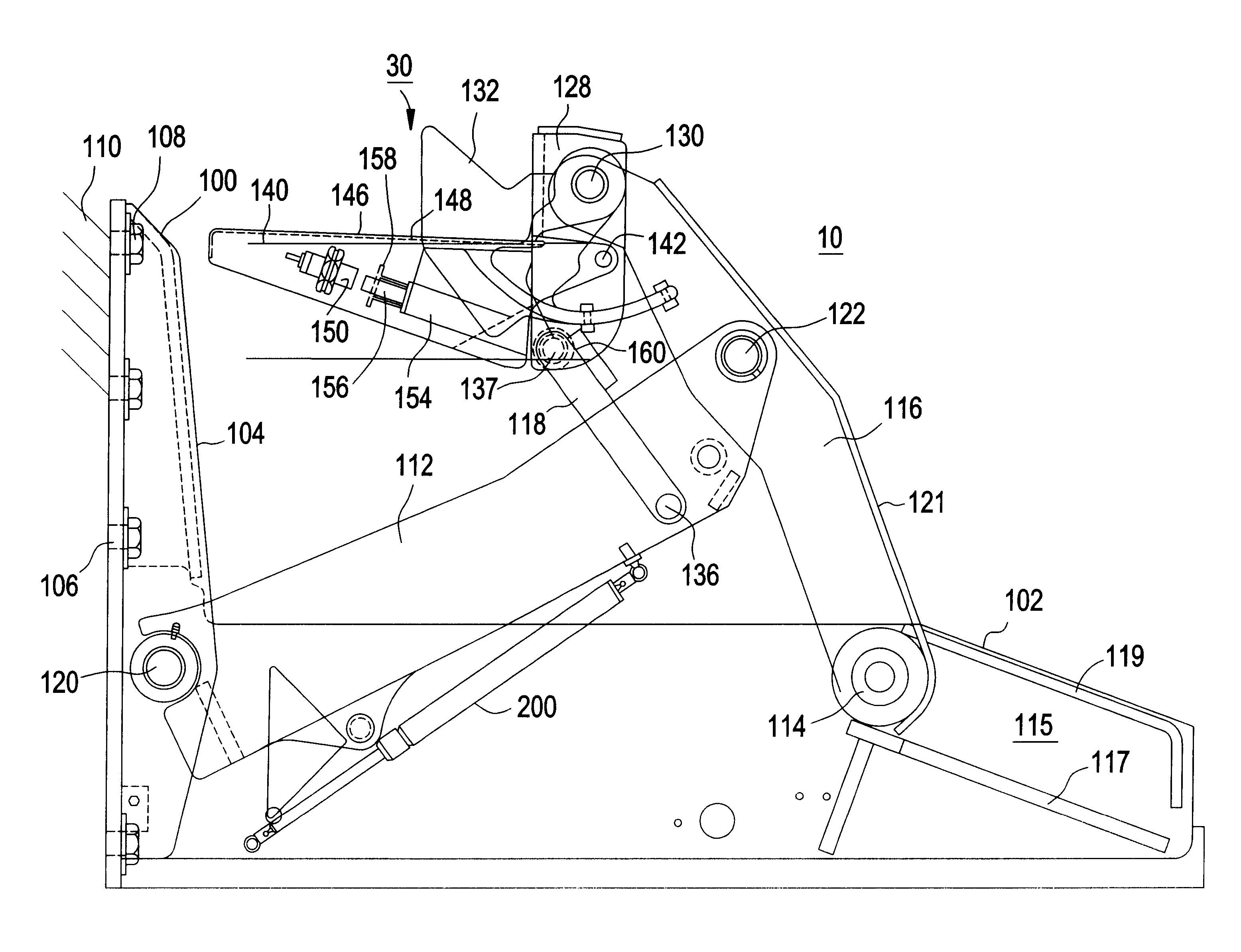
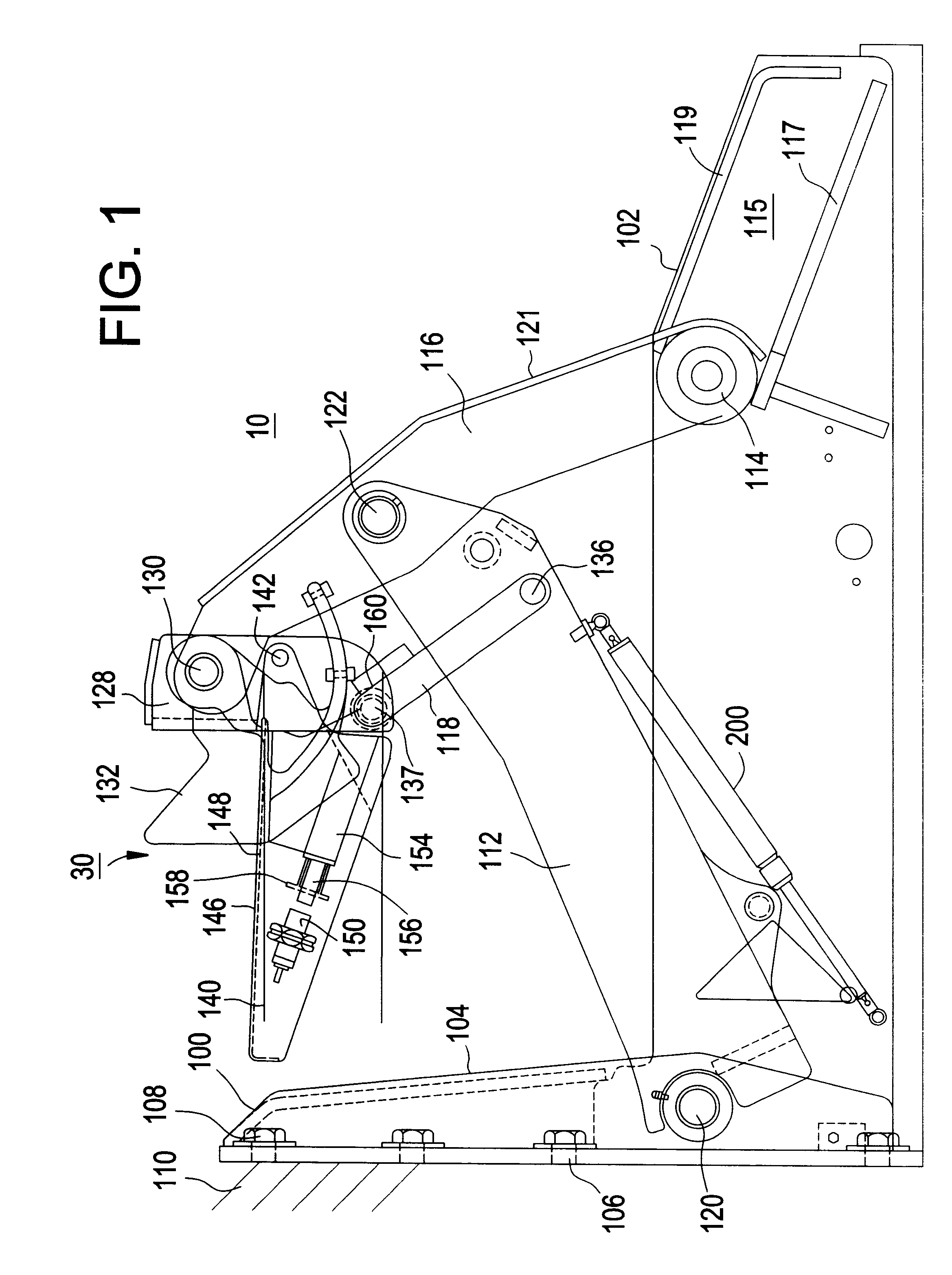
Referring now to FIG. 1, a vehicle restraint 10 is positioned on the driveway 1 and secured to a dock wall.

A frame 100 includes a housing 102 and a back-frame 104. The back-frame has a series of holes 106 with anchor bolts 108 to facilitate mounting to the wall 110 of a loading dock. While not illustrated, the device may be ground mounted by the use of legs attached to the bottom of the housing 102.

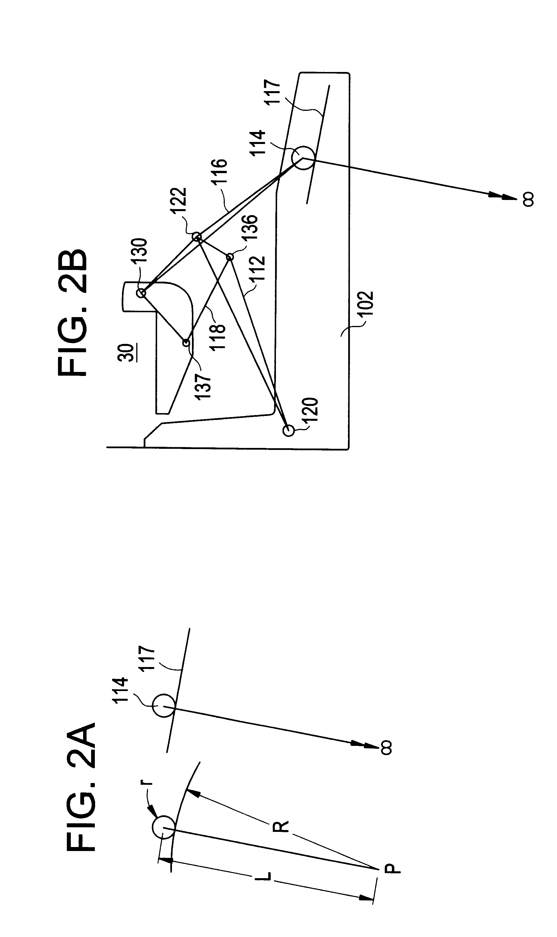
The linkage of this device will now be described. It is a departure from the 4-bar linkage of the Serco VR restraint, as described in U.S. Pat. No. 5,120,181. The linkage comprises a main arm, 112, an upper arm 116 and a hook strut 118. The main arm 112 is pivotally coupled to the frame at pivot pin 120. While FIG. 1 illustrates in side view one arm 112, the main arm comprises two such arms mounted to pivot pin 120 and attached to each side of the upper arm 116 at pin 122 as illustrated in FIG. 3. This configuration differs from the four-bar linkage of the prior art by the elimination of ...


PUM


Abstract

A vehicle restraint having a frame mounted to a dock face and a hook movable relative to the fixed member for engaging a portion of a vehicle and restraining movement of the vehicle away from the dock. The vehicle restraint has a linkage comprising a first arm pivotally connected to the frame, a second arm pivotally connected to the first arm and having a first end not fixed and movable with respect to the frame and a second end pivotally coupled to the hook, and a third arm coupling the first arm to the hook to maintain the hook in a generally vertical orientation. A sensor may be employed to determine engagement of the hook with a portion of the vehicle.

Description

I. BACKGROUND OF THE INVENTION1. Field of the InventionThis invention relates to an improved system for restraining a vehicle such as a transport truck or trailer which is to be restrained from movement at a loading dock. This invention is also related to a sensing system for use with such a vehicle restraint.2. Prior ArtA variety of techniques are known by which a vehicle is mechanically secured to prevent movement by using the ICC bar as the means to engage the truck or trailer. U.S. Pat. No. 4,127,856 Bickel describes the use of electrical switches to sense the engagement of the vehicle restraint with a bar mounted on the rear of a vehicle. The commercial use of locking devices is now well known in the art. For example, the Rite-Hite "Dok-Lok", Serco "VR" and Kelley "Truk Stop" and "Star" all have models that contact a vehicle ICC bar and constrain the truck from movement. Models of those systems generate signals to indicate that engagement has occurred so that personnel at the l...

Claims


Application Information

Patent Timeline
Patent Type & Authority Patents(United States)
IPC IPC(8): B65G69/00
CPCB65G69/003
Inventor ALEXANDER, JAMES C.
Owner UNITED DOMINION INDS
Why Eureka
Try Eureka