Cylindrical roller bearing

a technology of cylindrical roller bearing and roller bearing, which is applied in the direction of roller bearing, mechanical equipment, rotary machine parts, etc., can solve the problems of squeak noise, wear, damage to the bearing, etc., and achieve the effect of preventing the bearing from biting

Active Publication Date: 2019-08-22
NSK LTD
View PDF0 Cites 0 Cited by
  • Summary
  • Abstract
  • Description
  • Claims
  • Application Information

AI Technical Summary

Benefits of technology

[0025]According to the cylindrical roller bearing of the present embodiment, the column portions of the cage include roller holding portions which restrain the cylindrical roller on the outer diameter side and the inner diameter side thereof. The roller holding portions are formed such that for the radial movement amount of the cage with respect to the cylindrical roller, the outer diameter side movement amount<the inner diameter side movement amount, and the outer diameter side opening width of the pocket portion>the inner diameter side opening width of the pocket portion from the state where the revolution center of the cylindrical roller coincides with the axial center of the cage, and the column portion includes the inner diameter side protrusion which protrudes further to the inner diameter side than the inner circumferential surfaces of the annular portions and configures the roller holding portions. Accordingly, the cylindrical roller is guided on the outer diameter side of the column portion at low speed, the skew of the cylindrical roller is suppressed, and effects of preventing roller end surface wear, inner ring flange surface wear, and squeak noise are obtained. Further, since the cylindrical roller is guided on the inner diameter sides of the column portions having the opening width narrowed by the inner diameter side protrusion by the thermal expansion and the centrifugal expansion of the cage at high speed, the cylindrical roller can be prevented from biting into the column portions of the cage by the roller holding angle on the relatively narrow inner diameter side.

Problems solved by technology

However, when the outer ring guide type cage is used, if the lubrication of a guide surface is insufficient, wear occurs in a contact portion between the cage and a outer ring, and there is a possibility that the bearing is damaged.
Further, when assembly is performed in a positive radial gap due to variations in installation conditions, the roller may be easily skewed or tilted, and the generation of squeak noise and wear between an inner ring flange surface and a roller end surface due to revolution slip and the like may occur.

Method used


Image

  • Cylindrical roller bearing
  • Cylindrical roller bearing
  • Cylindrical roller bearing

Examples


first embodiment

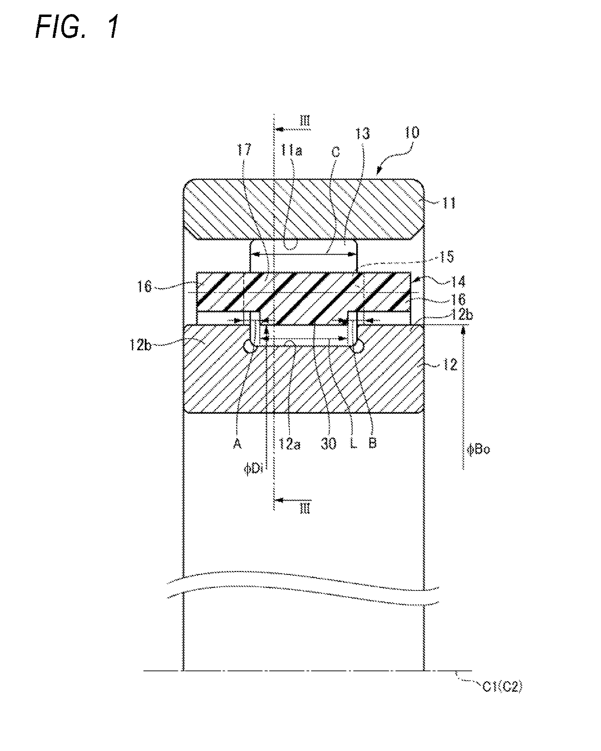
[0039]As shown in FIG. 1, a cylindrical roller bearing 10 includes an outer ring 11 having an outer ring raceway surface 11a formed on an inner circumferential surface, an inner ring 12 having an inner ring raceway surface 12a formed on an outer circumferential surface, a plurality of cylindrical rollers 13 rollably disposed between the outer ring raceway surface 11a and the inner ring raceway surface 12a, and a roller guide type resin cage 14 forming a plurality of pocket portions 15 which rotatably hold the plurality of cylindrical rollers 13 respectively. The inner ring 12 includes flange portions 12b, 12b at both axial end portions of the inner ring raceway surface 12a.

[0040]The cylindrical roller bearing 10 may be lubricated with any lubricant of lubricating oil and grease.

[0041]The resin cage 14 is made of a synthetic resin material such as polyamide, polyacetal, polyether ether ketone, polyimide, and polyphenylene sulfide, and if necessary, a reinforcing material such as a g...

second embodiment

[0058]FIG. 5 is a cross-sectional view showing a cylindrical roller and a cage in a cylindrical roller bearing according to the second embodiment. In the present embodiment, the shape of the inner surface 19 of each of the roller holding portions 18, 18 is different from that of the first embodiment.

[0059]In the second embodiment, the inner surface 19 of each of the roller holding portions 18, 18 includes a flat surface 19a passing through the pitch circle diameter PCD position of the cylindrical roller 13 and concave circular arc surfaces 19b, 19c formed on the outer diameter side and the inner diameter side of the flat surface 19a.

[0060]In the state where the revolution center C1 of the cylindrical roller 13 coincides with the axial center C2 of the cage 14, the circular arc surface 19b on the outer diameter side is concaved shape with a curvature radius R1 which has a center on the inner side with respect to the center O of the cylindrical roller 13 located on the pitch circle d...

third embodiment

[0062]FIG. 6 is a cross-sectional view showing a cylindrical roller and a cage in a cylindrical roller bearing according to the third embodiment. In the present embodiment, the shape of the inner surface 19 of each of the roller holding portions 18, 18 is different from that of the first embodiment.

[0063]In the third embodiment, the inner surface 19 of each of the roller holding portions 18, 18 includes the flat surface 19a passing through the pitch circle diameter PCD position of the cylindrical roller 13, a concave circular arc surfaces 19b formed on the outer diameter side of the flat surface 19a, and a tapered surface 19d formed on the inner diameter side of the flat surface 19a.

[0064]In the state where the revolution center C1 of the cylindrical roller 13 coincides with the axial center C2 of the cage 14, the circular arc surface 19b on the outer diameter side is concave shape with the curvature radius R1 which has center on the inner side with respect to the center O of the c...


PUM

PropertyMeasurementUnit
outer diameteraaaaaaaaaa
inner diameteraaaaaaaaaa
widthaaaaaaaaaa

Abstract

The column portions of the cage includes roller holding portions which restrain the cylindrical roller on an outer diameter side and an inner diameter side thereof. The roller holding portions are formed such that a radial movement amount of the cage with respect to the cylindrical roller from a state where a revolution center of the cylindrical roller coincides with an axial center of the cage is configured so that an outer diameter side movement amount<an inner diameter side movement amount, and an outer diameter side opening width of the pocket portion>an inner diameter side opening width of the pocket portion. The column portion includes an inner diameter side protrusion which protrudes to an inner diameter side than inner circumferential surfaces of the annular portions and which configures the roller holding portions.

Description

TECHNICAL FIELD[0001]The present invention relates to a cylindrical roller bearing, and particularly to a cylindrical roller bearing suitable for a machine tool spindle.BACKGROUND ART[0002]A single-row cylindrical roller bearing used in a machine tool spindle is often used at high speed rotation (for example, dmN (=(inner diameter of bearing+outer diameter of bearing) / 2×rotational speed (rpm)) is 350,000 to 700,000 or more) and under negative radial gap conditions. Under such severe use conditions, since a cage is subjected to a force due to mutual sliding with a roller, an outer ring guide type cage may be used.[0003]However, when the outer ring guide type cage is used, if the lubrication of a guide surface is insufficient, wear occurs in a contact portion between the cage and a outer ring, and there is a possibility that the bearing is damaged. Further, when assembly is performed in a positive radial gap due to variations in installation conditions, the roller may be easily skewed...

Claims


Application Information

Patent Timeline
Patent Type & Authority Applications(United States)
IPC IPC(8): F16C19/26F16C33/56
CPCF16C19/26F16C33/56F16C2208/60F16C2208/40F16C2208/52F16C33/4635F16C33/4676F16C2220/04F16C2240/44F16C2240/46F16C2240/70F16C2322/39F16C33/467F16C33/541F16C33/54
Inventor SOGA, SHUJI
Owner NSK LTD
Why Eureka
Try Eureka