End Plate, Battery Module, Battery Pack Comprising the Battery Module and Vehicle Comprising the Battery Pack

a battery module and end plate technology, applied in the direction of batteries, cell components, vehicle sub-unit features, etc., can solve the problems of cell expansion, product reliability degradation, subsequent swelling control problem, etc., and achieve the effect of reducing volume and weight, preventing the shape change of the battery module, and reducing the volume of the battery modul

Active Publication Date: 2019-08-29
LG ENERGY SOLUTION LTD
View PDF0 Cites 12 Cited by
  • Summary
  • Abstract
  • Description
  • Claims
  • Application Information

AI Technical Summary

Benefits of technology

[0028]According to the present disclosure, it is possible to prevent the shape changes of the battery module caused by swelling phenomena.
[0029]More specifically, the end plate according to the present disclosure is formed by bending a sheet and thus has the reduced volume and weight, thereby reducing the volume of the battery module and increasing the energy density.

Problems solved by technology

In the case of the pouch-type secondary battery, gas may be generated as a result of decomposition of an electrolyte solution therein due to side reactions caused by repeated charging / discharging, resulting in cell expansion.
However, when the buffer 2 is inserted between the battery cells 1 to control swelling, because the soft element is applied, it is difficult to apply the initial pressure to the battery cell 1, and according to the properties of the soft material, the element may wear over time, and as a consequence, may be vulnerable to deformation, causing a subsequent swelling control problem and product reliability degradation.
Accordingly, in the manufacture of the battery module, the manufacturing costs increase and the volume and weight of the battery module increases.
Additionally, in case that swelling phenomena is prevented by the pressing type end plate 3 alone, it is difficult to control a thickness allowance of the unit battery cell when constructing a cell assembly composed of the plurality of battery cells 1.

Method used


Image

  • End Plate, Battery Module, Battery Pack Comprising the Battery Module and Vehicle Comprising the Battery Pack
  • End Plate, Battery Module, Battery Pack Comprising the Battery Module and Vehicle Comprising the Battery Pack
  • End Plate, Battery Module, Battery Pack Comprising the Battery Module and Vehicle Comprising the Battery Pack

Examples


Embodiment Construction

[0043]The above-described object, feature and advantage will be described in detail with reference to the accompanying drawings, and accordingly, those skilled in the art will easily practice the technical aspects of the present disclosure. In describing the present disclosure, when it is deemed that a certain detailed description of relevant known technology unnecessarily renders the key subject matter of the present disclosure ambiguous, the detailed description is omitted herein. Hereinafter, the preferred embodiments of the present disclosure will be described in detail with reference to the accompanying drawings. In the drawings, like reference numerals are used to indicate identical or similar elements.

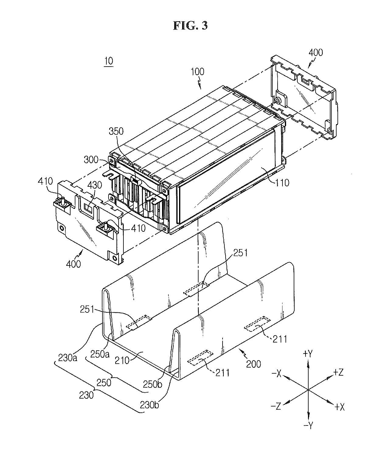
[0044]FIG. 3 is an exploded perspective view of a battery module according to an embodiment of the present disclosure, FIG. 4 is an exploded perspective view of a cell assembly included in the battery module according to an embodiment of the present disclosure, and FIG. 5 is a f...


PUM

PropertyMeasurementUnit
angleaaaaaaaaaa
angleaaaaaaaaaa
widthaaaaaaaaaa

Abstract

A battery module according to an embodiment of the present disclosure includes a cell assembly including a plurality of battery cells stacked side by side in a horizontal direction, each battery cell defining a respective plane extending in a vertical direction perpendicular to the horizontal direction, and an end plate having a support part configured to support a bottom of the cell assembly, an outer side part extending in the vertical direction from an end of the support part, and an inner side part extending downward and inward from a top of the outer side part.

Description

TECHNICAL FIELD[0001]The present application is a national phase entry under 35 U.S.C. § 371 of International Patent Application No. PCT / KR2018 / 003930, filed on Apr. 3, 2018, published in Korean, which claims priority from Korean Patent Application No. 10-2017-0044946, filed on Apr. 6, 2017, the disclosures of which are hereby incorporated herein by reference.[0002]The present disclosure relates to an end plate, a battery module, a battery pack comprising the battery module and a vehicle comprising the battery pack, and more particularly, to an end plate for preventing the shape changes of a battery module caused by swelling phenomena, a battery module, a battery pack comprising the battery module and a vehicle comprising the battery pack.BACKGROUND ART[0003]Due to its characteristics of being easily applicable to various products and electrical characteristics such as high energy density, a secondary battery is not only commonly applied to a portable device, but universally applied...

Claims


Application Information

Patent Timeline
Patent Type & Authority Applications(United States)
IPC IPC(8): H01M2/10B60L50/64B60K6/28H01M50/211
CPCH01M2/1077B60L50/64B60K6/28H01M2220/20B60Y2200/91B60Y2200/92B60Y2400/112H01M2/1083H01M10/0481Y02T10/70Y02E60/10H01M50/211H01M50/20H01M50/24
Inventor PARK, JIN-YONGMUN, JEONG-OCHI, HO-JUNE
Owner LG ENERGY SOLUTION LTD
Why Eureka
Try Eureka