
Method and system for predicting the time required for low voltage expression of a secondary battery, and aging method of the secondary battery using the same

Active Publication Date: 2019-09-05
LG ENERGY SOLUTION LTD
View PDF1 Cites 5 Cited by
  • Summary
  • Abstract
  • Description
  • Claims
  • Application Information

AI Technical Summary

Benefits of technology

The present invention provides a method to predict the time required for a secondary battery to reach low voltage and the aging process time. This allows for faster aging and increased defect detection, preventing defective cells from being shipped out.

Problems solved by technology

However, insulation may not be properly maintained due to various reasons during the manufacturing process of the battery.
As a result, an internal short circuit of the battery can occur.
Soft-shorts cause low-voltage defects.
However, the secondary battery may become further defective during the storage period until the secondary battery is inserted into the battery pack after the activation process is completed.
In addition, a product to be judged as a low-voltage defect may be erroneously determined as a normal product and may be put into a battery pack together.
Particularly, although the low voltage defect due to the soft short is measured by measuring the voltage fluctuation width through the aging process after the manufacture of the battery, it is difficult to select the low voltage defect within a short period of time.
In the conventional defective sorting process, although a difference in voltage drop between good and defective products is used, there is a problem that failure cannot be detected properly when the time for low voltage expression takes a long time.
However, it is undesirable to perform the aging process for a long time until a low voltage failure is manifested because it decreases the productivity.

Method used


Image

  • Method and system for predicting the time required for low voltage expression of a secondary battery, and aging method of the secondary battery using the same
  • Method and system for predicting the time required for low voltage expression of a secondary battery, and aging method of the secondary battery using the same
  • Method and system for predicting the time required for low voltage expression of a secondary battery, and aging method of the secondary battery using the same

Examples


Embodiment Construction

[0041]Hereinafter, the present invention will be described more specifically with reference to the accompanying drawings. It is to be understood that the following detailed description and drawings are merely illustrative of the embodiments of the present invention, and therefore the present invention should not be construed as being limited to the description and contents.

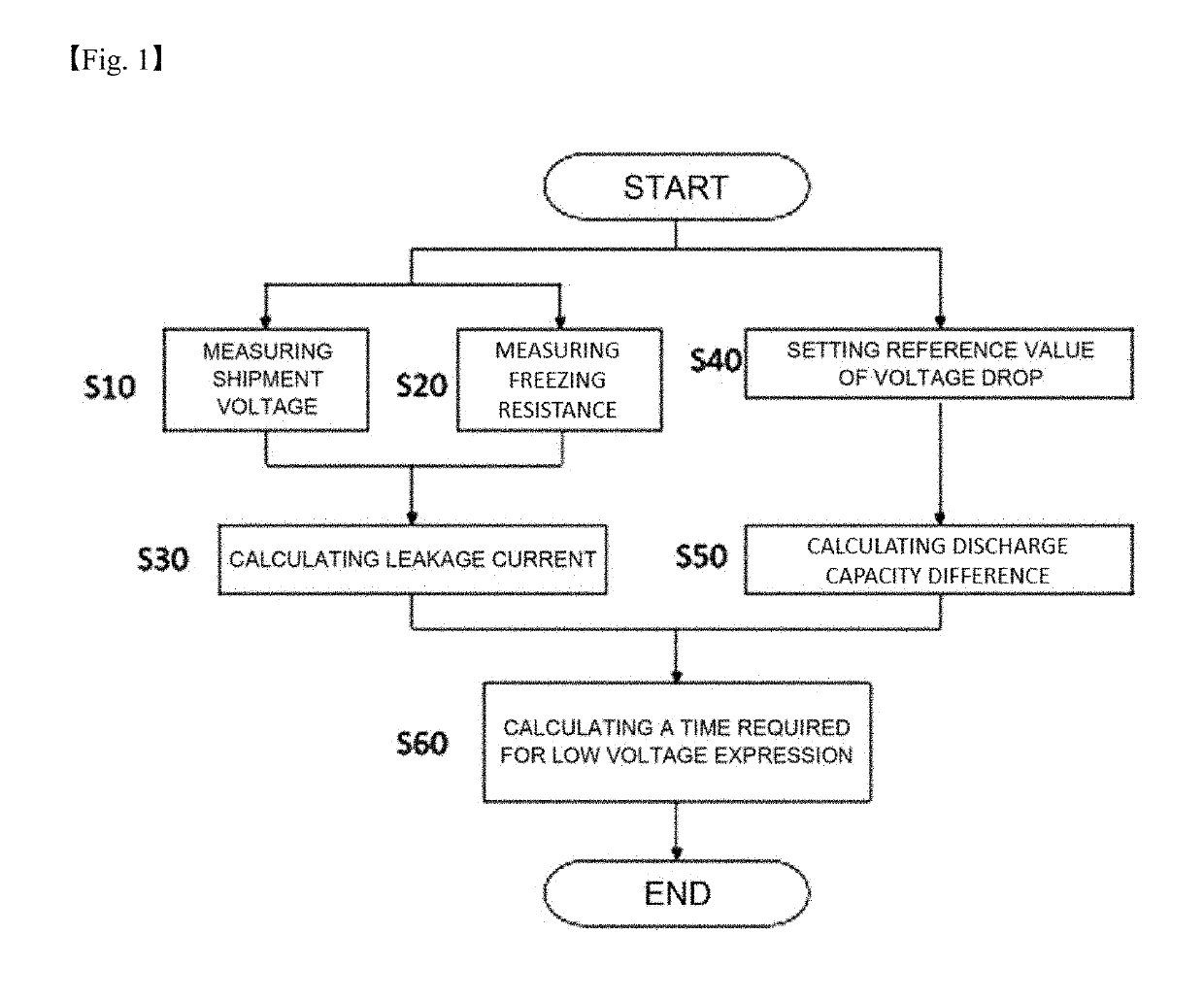
[0042]First, the terms used in the present invention will be described. The term ‘shipment voltage (V)’ in the present invention means an initial charging voltage when a lithium secondary battery is manufactured and shipped from a factory.

[0043]In the present invention, terms such as “a” and “a-1” are used as in “step (a)”, “sub-step (a-1)”, but it is to be understood that these terms are used to distinguish the process steps and the like from each other in order to facilitate understanding of the present invention, and the scope of the present invention should not be unduly construed by these terms.

[0044]The pres...


PUM


Abstract

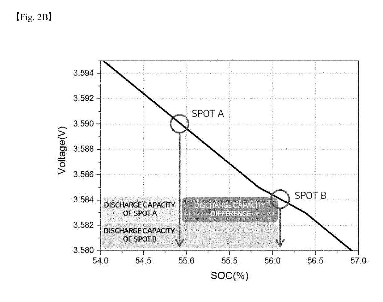
A method and system for predicting the time required for low voltage expression of a secondary battery, including (a) obtaining a leakage current by inputting a voltage of a battery cell of the secondary battery, measuring a freezing resistance of a battery cell, and dividing an input voltage by a measured freezing resistance, (b) obtaining a discharge capacity difference by setting a reference value of a voltage drop for selecting a low voltage defect and obtaining a discharge capacity difference between the input voltage and a voltage dropped therefrom by the reference value, and (c) dividing the discharge capacity difference by the leakage current to thereby calculate a time required for low voltage expression.

Description

TECHNICAL FIELD[0001]The present invention relates to a method and system for predicting the time required for low voltage expression of a secondary battery, and a method for aging the secondary battery using the same, and more particularly, to a method and system for predicting the time required for low voltage expression of a secondary battery, which can improve the productivity by reducing the unnecessary aging time by predicting the low voltage expression time of the secondary battery and using the predicted low voltage expression time and can enhance the detection rate of defective batteries, and a method of aging the secondary battery using the method and system.BACKGROUND ART[0002]As technology development and demand for mobile devices are increasing and the spread of electric vehicles is expanding, demand for secondary batteries as energy sources is rapidly increasing. Among them, demand for lithium secondary batteries having high capacity and energy density is especially hi...

Claims


Application Information

Patent Timeline
IPC IPC(8): G01R31/392G01R31/3842G01R31/388H01M10/48G01R31/389
CPCG01R31/392G01R31/3842G01R31/389H01M10/48G01R31/388H01M10/4285H01M10/446G01R31/52Y02E60/10G01R31/3865Y02P70/50G01R31/3648G01R19/16571G01R19/16576H01M10/049H01M4/0447
Inventor KIM, SO HEESUNG, NAK GIBAE, JOON SUNG
Owner LG ENERGY SOLUTION LTD
Learn More