Ion transport device and ion mobility spectrometer

a technology of ion transport and mobility spectrometer, which is applied in the direction of electron/ion optical arrangement, particle separator tube details, instruments, etc., can solve the problems of easy fracture of ceramic spacers, brittle ceramic materials, and high cost of ceramic parts if produced, so as to reduce the cost of spacers, easy fracture, and easy fracture

Inactive Publication Date: 2019-09-05
SHIMADZU CORP
View PDF0 Cites 5 Cited by
  • Summary
  • Abstract
  • Description
  • Claims
  • Application Information

AI Technical Summary

Benefits of technology

[0032]According to the present invention, it is possible to decrease the cost of the spacers used for defining the intervals of the electrodes in an ion transport device (or ion mobility spectrometer) while securing electrical insulation and other performances of the device. This contributes to a cost reduction of the entire device. Additionally, the spacers used in the present invention do not easily fracture and can be easily assembled.

Problems solved by technology

However, ceramic parts will be expensive if they are produced in small quantities, as in the case of analytical devices.
Another problem is that ceramic materials are brittle.
Ceramic spacers easily fracture in the process of creating a structure in which ceramic spacers and electrodes are alternately stacked.
However, when used in the drift unit of an ion mobility spectrometer, PEEK may be insufficiently resistant to heat since the drift unit is heated to high temperatures (e.g. approximately 150° C. or higher).
However, the gas which results from the pyrolysis and volatilization of the synthetic resin may become contaminations for the analysis.

Method used


Image

  • Ion transport device and ion mobility spectrometer
  • Ion transport device and ion mobility spectrometer
  • Ion transport device and ion mobility spectrometer

Examples


first embodiment

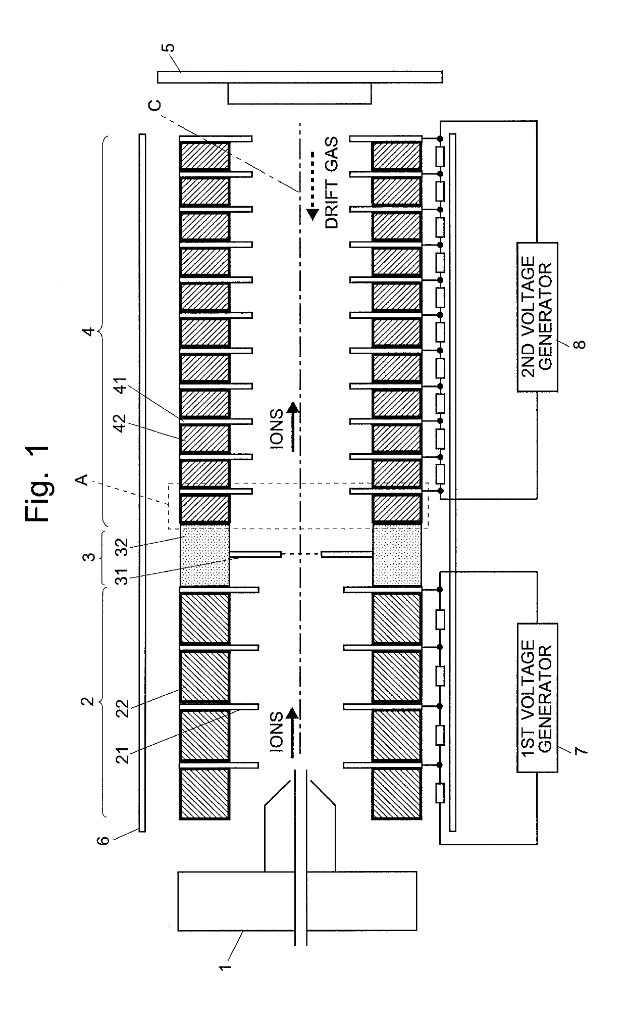
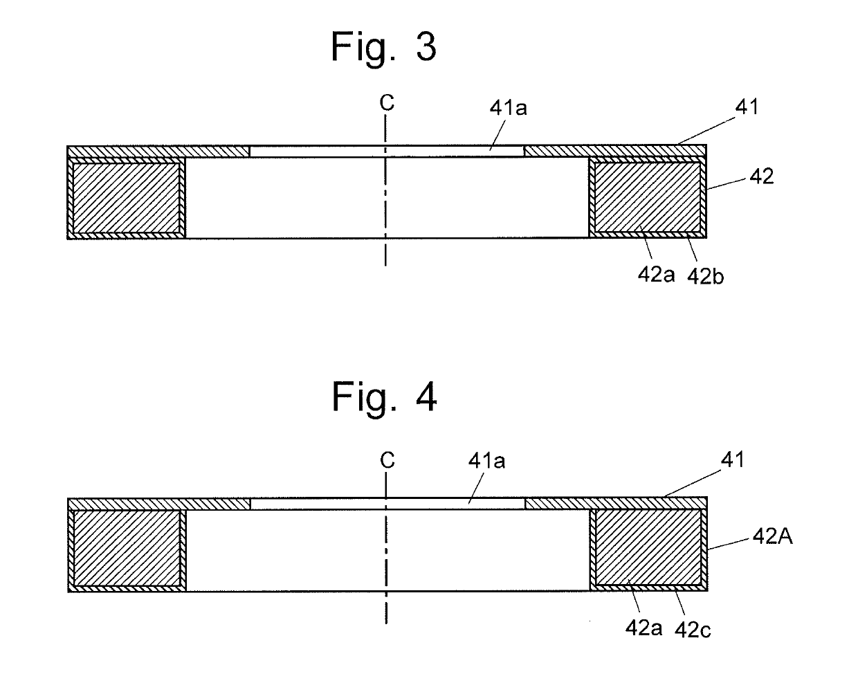
[0048]FIG. 1 is a schematic configuration diagram of an ion mobility spectrometer using an ion transport device as the first embodiment of the present invention. FIG. 3 is a sectional view of one flat-ring-shaped electrode and one spacer (the portion indicated by reference sign A in FIG. 1) in the ion transport device according to the first embodiment. It should be note that the electrodes and the spacers in FIG. 1 are shown by an end view in order to prevent the drawing from being complex, whereas the electrode and the spacer in FIG. 3 are shown by a sectional view. The same also applies in any of the following embodiments.

[0049]As shown in FIG. 1, the ion mobility spectrometer according to the present embodiment includes an ion source 1 for ionizing components in a liquid sample, an ionization-promoting unit 2 for promoting the ionization, a gate electrode unit 3 for temporarily blocking ions and subsequently releasing them in a pulsed form, a drift unit 4 for making ions drift, a...

second embodiment

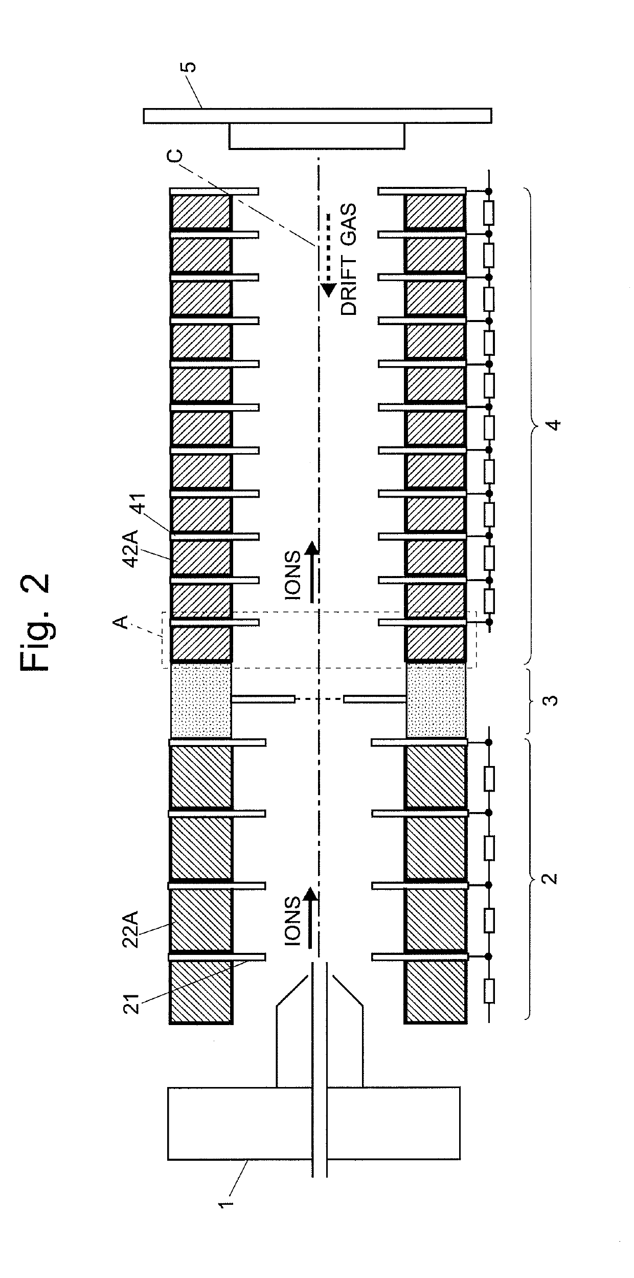
[0063]FIG. 2 is a schematic configuration diagram of an ion mobility spectrometer using an ion transport device as the second embodiment of the present invention. FIG. 4 is a sectional view of one flat-ring-shaped electrode and one spacer in the ion transport device according to the second embodiment. The same components as used in the first embodiment are denoted by the same reference signs, and detailed descriptions of those components will be omitted.

[0064]In the ion transport device according to the first embodiment, the insulation film 42b was formed on the entire surface of the base body 42a of the spacer 42. By comparison, in the ion transport device according to the second embodiment, as shown in FIG. 4, the insulation film 42c does not cover the entire surface of the base body 42a; the base body 42a is exposed on the side on which the base body 42a is in contact with one electrode 41. On the opposite side of the base body 42a, which is in contact with another electrode 41 t...

third embodiment

[0067]FIG. 5 is a schematic configuration diagram of an ion transport device as the third embodiment of the present invention. FIG. 6 is a sectional view of one flat-ring-shaped electrode and one spacer in the ion transport device according to the third embodiment. FIG. 5 shows the portion corresponding to the drift unit 4 in the ion mobility spectrometer as shown in FIG. 1 or 2. The same components as used in the previous embodiments are denoted by the same reference signs, and detailed descriptions of those components will be omitted.

[0068]Similar to the second embodiment, the insulation film 42d is not formed on the surface of the base body 42a at the portion where the spacer 42B is in contact with one electrode 41; the base body 42a is in direct contact with the electrode 41 at this portion. By comparison, the insulation film 42d is formed at the portion where the spacer 42B is in contact with another electrode 41 adjacent to the one aforementioned electrode 41, thereby securing...


PUM

PropertyMeasurementUnit
temperaturesaaaaaaaaaa
temperatureaaaaaaaaaa
pressureaaaaaaaaaa

Abstract

Annular members having an aluminum base body coated with an insulation film formed by hard alumite processing are used as spacers (42A) alternately arrayed with flat-ring-shaped electrodes (41) along an axis (C). The insulation film provides electrical insulation between the electrodes (41) neighboring each other. This film is omitted on one side of the spacer (42A) so that the base body of this spacer is in contact with and electrically connected to one of the two electrodes (41) between which the spacer (42A) is sandwiched. Voltages applied to the electrodes (41) give specific potentials to the spacers (42A), thereby enabling the spacers (42A) to serve as a shield electrode which reduces the influence of an external electric field on an electric field within a drift unit (4). The use of such spacers decreases the cost of an ion transport device used for a drift region in an ion mobility spectrometer.

Description

TECHNICAL FIELD[0001]The present invention relates to an ion transport device for transporting ions of sample-component origin by using an electric field, as well as an ion mobility spectrometer employing such an ion transport device.BACKGROUND ART[0002]When a molecular ion generated from a sample molecule is made to move through a gaseous (or liquid) medium by an effect of an electric field, the ion moves at a constant speed depending on its mobility which is determined by the strength of the electric field, size of the molecule and other factors. Ion mobility spectrophotometry (IMS) is a measurement technique which utilizes this mobility for an analysis of sample molecules. Typically, IMS is used in a device which separates various sample-derived ions from each other according to their ion mobilities and subsequently detects those ions with a detector to create an ion mobility spectrum. Such a device is often used in combination with a mass analyzer.[0003]An ion mobility spectrome...

Claims


Application Information

Patent Timeline
Patent Type & Authority Applications(United States)
IPC IPC(8): H01J49/06G01N27/62
CPCG01N27/622H01J49/062
Inventor MORIHISA, YUJIIMAZU, AKIKO
Owner SHIMADZU CORP
Why Eureka
Try Eureka