Heat exchanger

a technology of heat exchanger and heat exchanger plate, which is applied in the direction of lighting and heating apparatus, turbines, manufacturing tools, etc., can solve the problems of significant mechanical energy loss of the first fluid, construction that cannot meet the dimensional and geometric tolerances required for manufacturing, and production difficulties

Pending Publication Date: 2019-09-12
SAFRAN
View PDF7 Cites 8 Cited by
  • Summary
  • Abstract
  • Description
  • Claims
  • Application Information

AI Technical Summary

Benefits of technology

[0017]Such geometric characteristics associated with the fins make it possible, with an equal mass, not only to significantly improve the aerothermal performances of the exchanger, but also to respect the desired dimensional and geometric tolerances, when it is obtained by additive manufacturing by selective melting on powder beds.
[0018]Indeed, on the one hand, such geometric characteristics make it possible to significantly reduce the recirculation region in the flow at the level of each of the leading edges (first edge or second edge according to the direction of the flow) of the fins, and consequently, to reduce the mechanical energy losses. This reduction is all the more significant, due to there being no variations in the cross-sections for the passage of the first fluid. In comparison, with respect to the heat exchangers of the prior art, it is estimated that the reduction of the charge losses is around 15%.

Problems solved by technology

Such an architecture has, in particular, the disadvantage of leading to a significant loss of mechanical energy from the first fluid, partially due to the presence of a recirculation region in the flow at the level of each of the leading edges of the fins.
Furthermore, by SLM manufacturing, in a vertical orientation (plates and fins perpendicular to the construction support), such an architecture does not make it possible to respect the dimensional and geometric tolerances required from manufacturing.
Indeed, the melting of an overhanging layer, of which the normal is parallel with the direction of adding layers, poses production difficulties, in particular due to the fact that only the non-melted powder serves as a support during the melting of such an overhanging layer.

Method used


Image

  • Heat exchanger
  • Heat exchanger
  • Heat exchanger

Examples


first embodiment

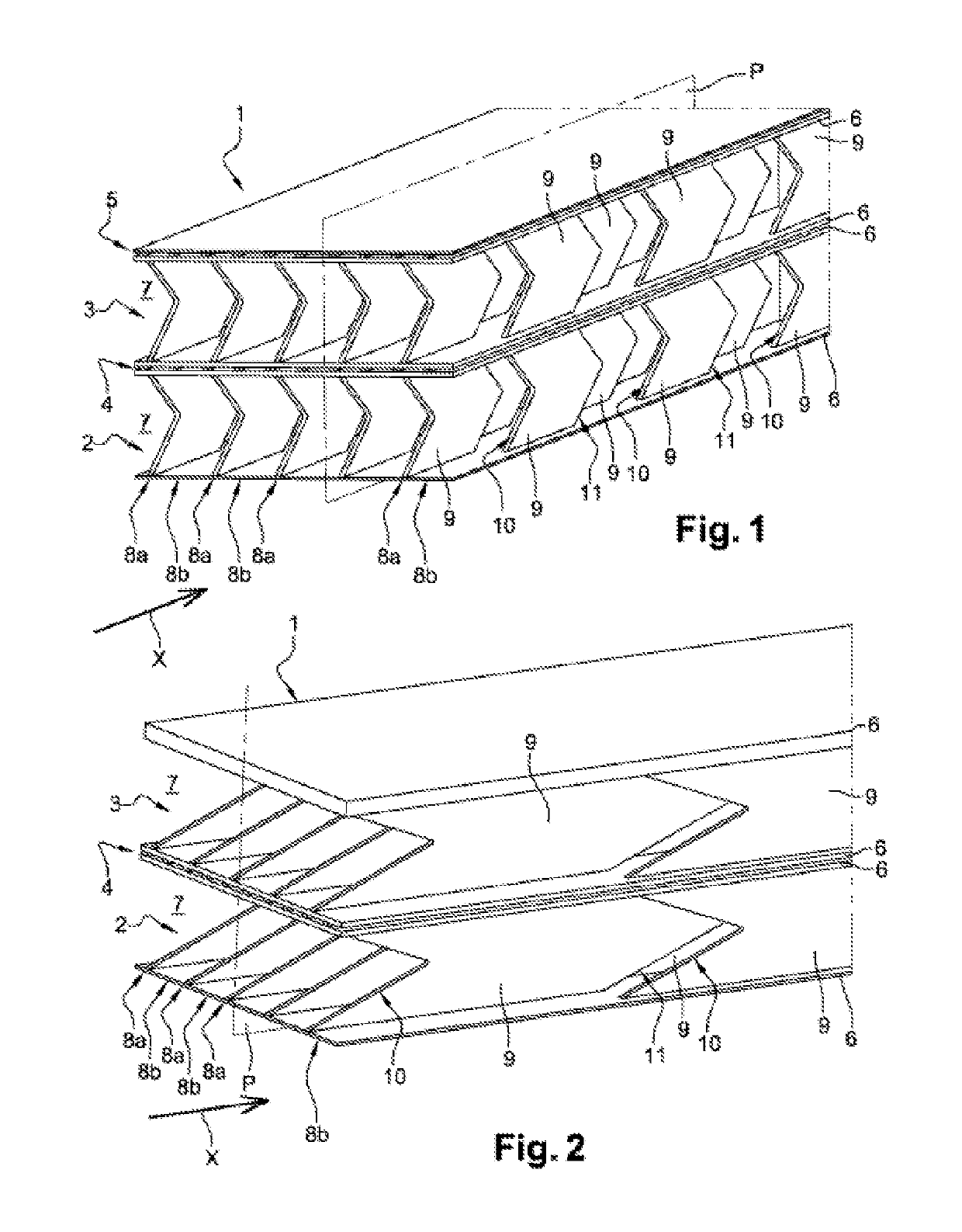
[0031]FIGS. 1 and 2 are perspective views of a heat exchanger (with two stages) according to the invention, each stage comprising two plates and a plurality of rows of fins arranged between the plates, ;

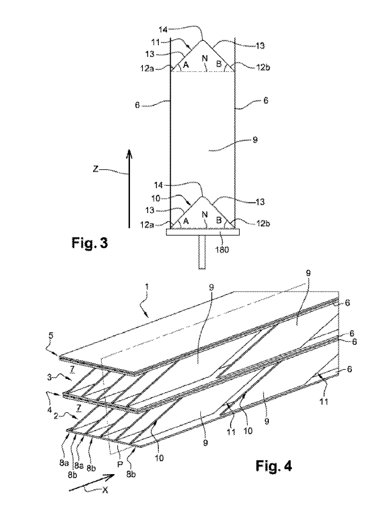
[0032]FIG. 3 is a detailed view of a fin of the heat exchanger of FIGS. 1 and 2, in a plane P;

second embodiment

[0033]FIG. 4 is a perspective view of a heat exchanger, ;

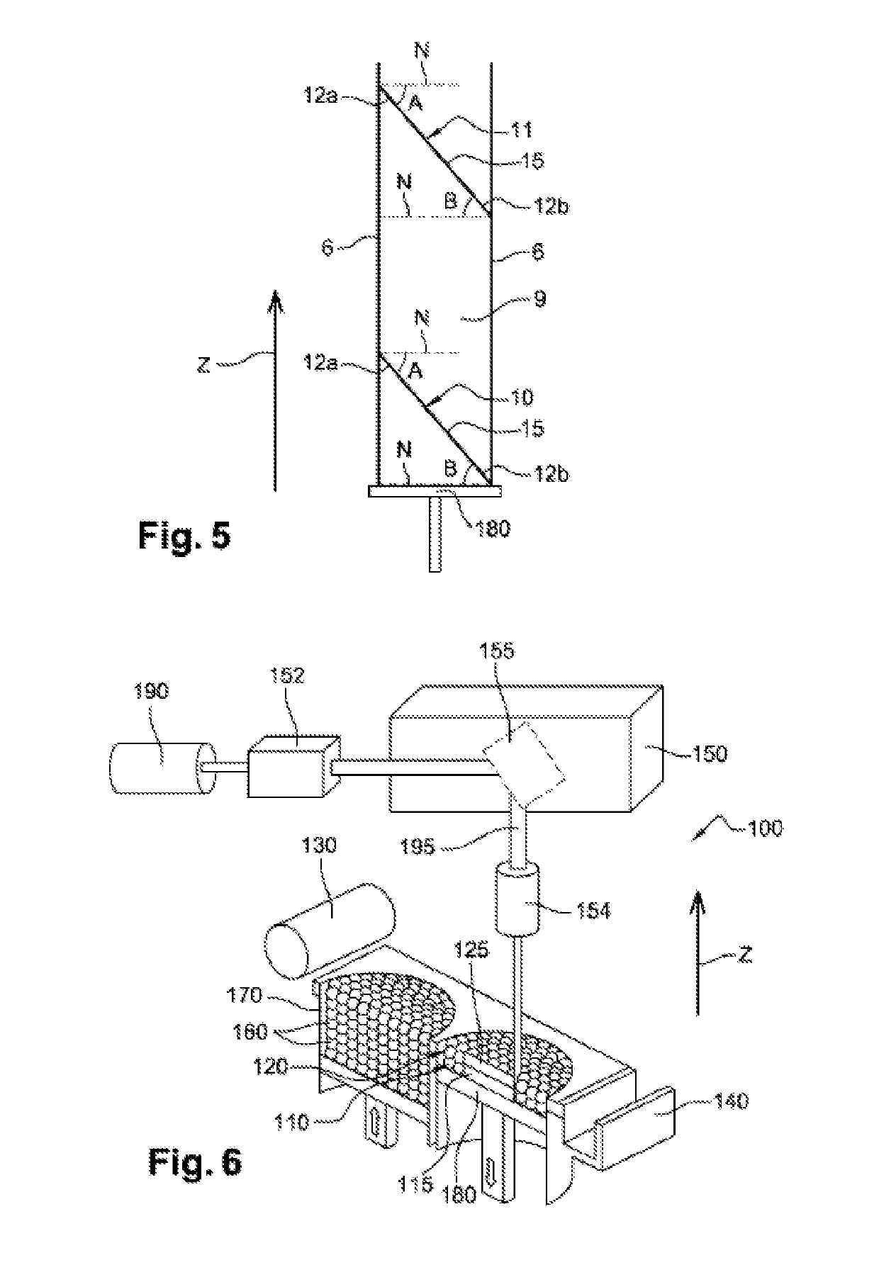
[0034]FIG. 5 is a detailed view of a fin of the heat exchanger of FIG. 4, in a plane P;

[0035]FIG. 6 is a schematic view of a machine for producing an exchanger (or an exchanger stage) according to the invention, by additive manufacturing;

[0036]FIGS. 7 to 10 are detailed views, in a plane P, similar to those of FIGS. 3 to 5, and illustrate embodiment variants of the fins according to the invention.

DETAILED DESCRIPTION

[0037]In FIGS. 1 and 2, a heat exchanger 1 between a first fluid (for example, hot exhaust gases) flowing in a longitudinal direction X and a second fluid (for example, air) is represented.

[0038]More specifically, the exchanger 1 is staged, namely a first and a second stage 2, 3 for circulating the first fluid. A first path 4 for circulating the second fluid is arranged between the first and second stages 2, 3 (inter-stage circulation path). A second path 5 for circulating the second fluid (not represented in FIG. ...

third embodiment

[0074] represented in FIG. 9, for each fin 9, in a plane P, the first edge 10 comprises one single concave elliptical section 21. The elliptical section 21 corresponds to an elliptical section having an angle at the centre substantially equal to 90° (quarter of an ellipsis) and is connected to one of the plates 6 via a fillet 22 (concave shape).


PUM

PropertyMeasurementUnit
angleaaaaaaaaaa
angleaaaaaaaaaa
angleaaaaaaaaaa

Abstract

Exchanger (1) of heat between a first fluid flowing in a longitudinal direction (X) and a second fluid, the said exchanger (1) comprising:two parallel plates (6) distant from one another;at least a first and second row (8a, 8b) of fins (9) arranged perpendicularly between the said plates (6), each fin (9) being delimited longitudinally by a first edge (10) and a second edge (11), the said first edge (10) comprising at each of its ends a region of connection with the corresponding plate (6);characterised in that the said connection regions of the said first edge (10) are respectively inclined with respect to a normal to the plates (6) in a plane (P) perpendicular to the said plates (6) and parallel with the direction (X), the said first edge (10) and the said second edge (11) of each of the fins (9) having identical profiles in the said plane (P).

Description

TECHNICAL FIELD[0001]The present invention relates to heat exchangers, in particular for a turbine engine.STATE OF THE ART[0002]A turbine engine comprises a gas generator comprising, for example, from upstream to downstream in the gas flow direction, one or more compressor stages, a combustion chamber, one or more turbine stages, and a nozzle for ejecting exhaust gases.[0003]A heat exchanger is installed in a turbine engine to make it possible for thermal energy transfer from one fluid to another.[0004]Such a heat exchanger is, for example, used to transfer thermal energy from hot exhaust gases to a gas intended to be introduced upstream of the combustion chamber, favouring, in particular, the fuel consumption of the turbine engine. This heat exchanger can also be used to cool the lubricant (for example, oil) of the different means for guiding the rotors of the gas generator.[0005]Such an exchanger is, for example, obtained by additive manufacturing by selectively melting on powder ...

Claims


Application Information

Patent Timeline
Patent Type & Authority Applications(United States)
IPC IPC(8): F28D21/00B23K26/342B33Y80/00F28D9/00F28F3/04F28F21/08
CPCF28F1/06F28F1/00F28F3/048B23K2101/001F28D9/0062B23K26/342F28D21/001B33Y80/00F28F21/08F28D21/0003F28F3/06F28D9/0081F28F2255/18B22F5/009B22F12/44B22F12/49B22F10/73B22F10/28F28D9/00F28F3/02Y02P10/25
Inventor TOUBIANA, EPHRAIM
Owner SAFRAN
Why Eureka
Try Eureka