Circularly polarizing plate, display device, and multilayer retarder

a technology of display devices and retarders, applied in the direction of polarizing elements, diodes, instruments, etc., can solve the problems of reducing the thickness of circularly polarizing plates, unable to achieve wide viewing angles, and significant internal reflection in display panels, so as to achieve wide range functionality and wide viewing angles

Active Publication Date: 2019-09-12
SHARP KK
View PDF0 Cites 33 Cited by
  • Summary
  • Abstract
  • Description
  • Claims
  • Application Information

AI Technical Summary

Benefits of technology

[0009]The present inventors made various studies on methods for producing a reverse wavelength dispersion λ / 4 plate reducible in thickness so as to achieve a circularly polarizing plate reducible in thickness and having both wide-range functionality and a wide viewing angle. The studies found that although it is difficult to produce a single-layer reverse wavelength dispersion λ / 4 plate from a typical material by a typical process, it is possible to provide substantially the same function as a single-layer reverse wavelength dispersion λ / 4 plate to a multilayer reverse wavelength dispersion λ / 4 plate by stacking a first retardation layer having negative refractive index anisotropy and a second retardation layer having positive refractive index anisotropy, which have different wavelength dispersibilities, such that their optical axes are parallel to each other. The two retardation layers may be made of a positive wavelength dispersion material or any other material, so that the first retardation layer and the second retardation layer can also be coating retarders. Thereby, the present inventors successfully achieved the above object, completing the present invention.
[0013]The present invention can provide a circularly polarizing plate and a multilayer retarder reducible in thickness and having both wide-range functionality and a wide viewing angle, and a display device including the circularly polarizing plate.

Problems solved by technology

For example, OLEDs, which include a cathode made of a metal, cause a significant internal reflection in the display panel.
Reducing the thickness of a circularly polarizing plate while achieving both of these optical properties has been highly difficult.
This method, however, causes the apparent crossing angle of the optical axes of the λ / 4 plate 53 and the λ / 2 plate 52 to be different depending on the viewing azimuth, failing to achieve a wide viewing angle.
This method, however, has difficulties in thinning the reverse wavelength dispersion λ / 4 plate 54, which is a modified polycarbonate resin film, enough for flexibilization, failing to reduce the thickness of the circularly polarizing plate.
Yet, typical polymerizable liquid crystals are a material with birefringence whose absolute value is lower for longer wavelengths, i.e., a positive wavelength dispersion material, which is effective in thickness reduction but cannot achieve wide-range functionality.

Method used


Image

  • Circularly polarizing plate, display device, and multilayer retarder
  • Circularly polarizing plate, display device, and multilayer retarder
  • Circularly polarizing plate, display device, and multilayer retarder

Examples


example 1

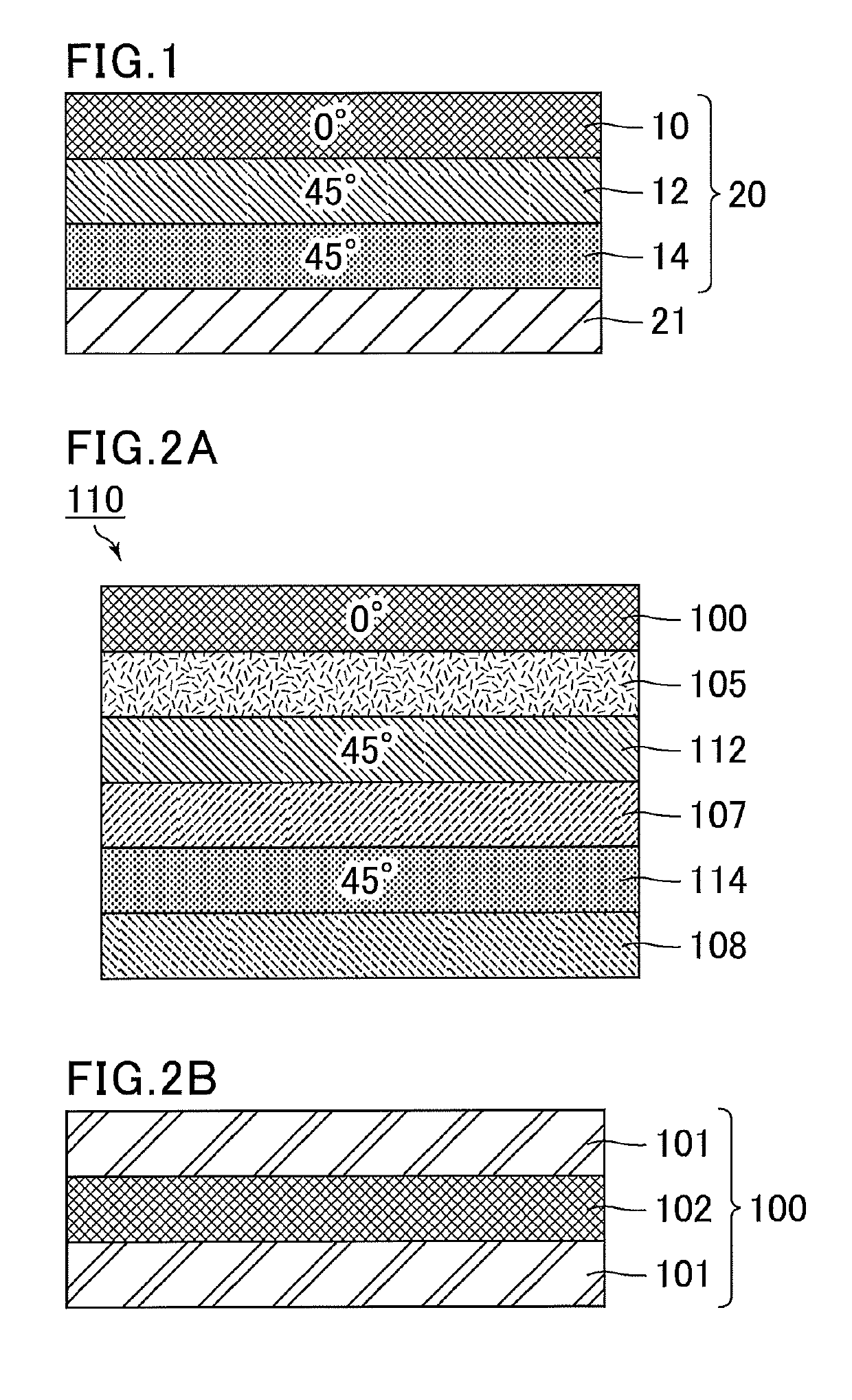
[0089]FIG. 2A is a schematic cross-sectional view showing the structure of a circularly polarizing plate of Example 1, and FIG. 2B is a schematic cross-sectional view showing the structure of a polarizing plate in the circularly polarizing plate of Example 1. A circularly polarizing plate 110 of Example 1 includes a stack of a polarizing plate 100 having a thickness of 65 μm, an adhesive 105 having a thickness of 12 μm, a retardation layer (A) 112 having a thickness of 1 μm, an alignment film 107 having a thickness of 0.1 μm, a retardation layer (B) 114 having a thickness of 2 μm, and an alignment film 108 having a thickness of 0.1 μm. The circularly polarizing plate of Example 1 has a thickness of 80 μm.

[0090]The polarizing plate 100 includes a stack of a protective film (TAC film) 101 having a thickness of 25 μm, an iodine-impregnated PVA film (polyvinyl alcohol film impregnated with iodine) 102 having a thickness of 15 μm, and a protective film 101 having a thickness of 25 μm.

[00...

examples 2 to 4

[0098]The circularly polarizing plates of Examples 2 to 4 are the same as the circularly polarizing plate of Example 1, except that the retardation values of the retardation layer (A) 112 and the retardation layer (B) 114 are changed as shown in the following Table 1. The reverse wavelength dispersion performance can be adjusted by changing the retardation values of the retardation layer (A) 112 and the retardation layer (B) 114.

example 5

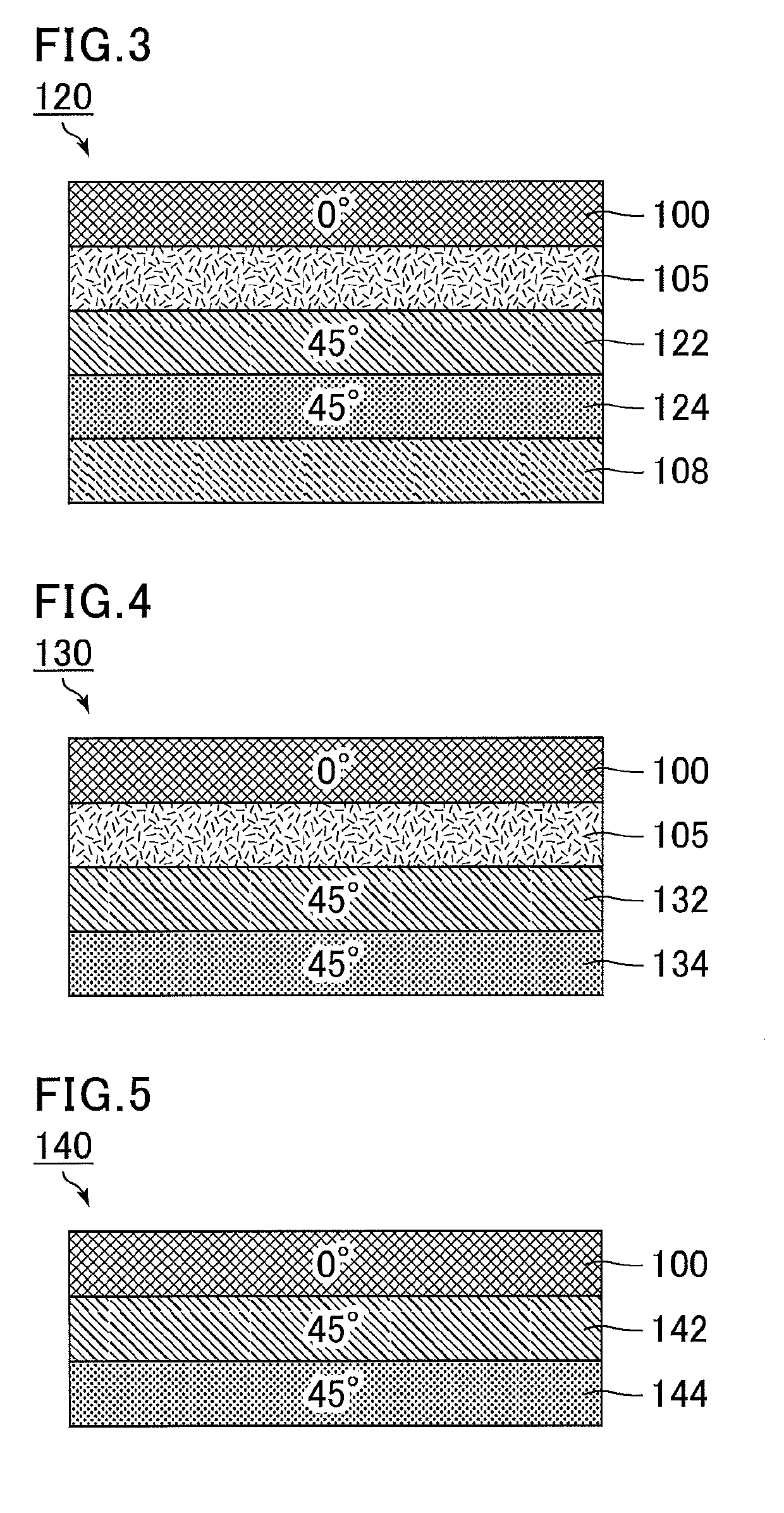
[0099]FIG. 3 is a schematic cross-sectional view showing the structure of a circularly polarizing plate of Example 5. A circularly polarizing plate 120 of Example 5 includes a stack of the polarizing plate 100 having a thickness of 65 μm, the adhesive 105 having a thickness of 12 μm, a retardation layer (A) 122 having a thickness of 1 μm, a retardation layer (B) 124 having a thickness of 2 μm, and the alignment film 108 having a thickness of 0.1 μm. The circularly polarizing plate of Example 5 has a thickness of 80 μm.

[0100]The optical characteristics of the circularly polarizing plate of Example 5 depend on the polarizing plate 100, the retardation layer (A) 122, and the retardation layer (B) 124. The retardation layer (A) 122 is a negative λ / 4 plate showing normal wavelength dispersion. The retardation layer (B) 124 is a positive λ / 2 plate showing normal wavelength dispersion. The retardation characteristics of the retardation layer (A) 122 and the retardation layer (B) 124 are sh...


PUM

PropertyMeasurementUnit
wavelengthaaaaaaaaaa

Abstract

A circularly polarizing plate includes: a first retardation layer having negative refractive index anisotropy; a second retardation layer having positive refractive index anisotropy; and a linear polarizer, the first retardation layer and the second retardation layer being disposed such that their optical axes are parallel to each other, the first retardation layer providing an in-plane retardation whose absolute value is |R1(λ)| to light having a wavelength of λ nm, the second retardation layer providing an in-plane retardation whose absolute value is |R2(λ)| to light having a wavelength of λ nm, the first retardation layer and the second retardation layer satisfying the following formulas (1) to (4):|R1(450)|>|R1(550)|>|R1(650)|  (1)|R2(550)|>|R1(550)|  (2)|R2(550)|−|R1(550)|>|R2(450)|−|R1(450)|  (3)|R2(650)|−|R1(650)|>|R2(550)|−|R1(550)|  (4)

Description

CROSS-REFERENCE TO RELATED APPLICATIONS[0001]The present application claims priority under 35 U.S.C. § 119 to Japanese Patent Application No. 2018-041917 filed on Mar. 8, 2018, the contents of which are incorporated herein by reference in their entirety.BACKGROUND OF THE INVENTIONField Of The Invention[0002]The present invention relates to circularly polarizing plates, display devices, and multilayer retarders. Specifically, the present invention relates to a circularly polarizing plate and a multilayer retarder which are suitable for a display device such as an organic electroluminescent display device or a liquid crystal display device, and to a display device including the circularly polarizing plate.Description of Related Art[0003]There is an increasing demand for flexibilization of display devices as typified by organic electroluminescent display devices (Organic Light Emitting Diodes: OLEDs) and liquid crystal display devices (LCDs), with the aim of achieving curved displays w...

Claims


Application Information

Patent Timeline
Patent Type & Authority Applications(United States)
IPC IPC(8): G02B5/30H01L27/32G02F1/1335G02F1/13363
CPCG02F1/13363G02F1/133528G02F2001/133541G02B5/3008H01L27/322G02F2001/133631H01L27/3244G02B5/3025G02B5/3033G02B5/3016G02B5/3083G02B5/3041H10K50/86G02F1/133541G02F1/133631H10K59/12H10K59/38
Inventor SAKAI, AKIRAHASEGAWA, MASAHIROMURATA, KOJIKAWAHIRA, YUICHIKOIDE, TAKAKOMINOURA, KIYOSHI
Owner SHARP KK
Why Eureka
Try Eureka