
Method of controlling air dryer using compressed air and heaterless air dryer thereof

a technology of compressed air and air dryer, which is applied in the direction of positive displacement liquid engine, braking system, separation process, etc., can solve the problems of air dryer, air dryer, and valve that cannot but lower the efficiency of mode switching control of air dryer

Active Publication Date: 2019-09-26
HYUNDAI MOTOR CO LTD +1
View PDF2 Cites 5 Cited by
  • Summary
  • Abstract
  • Description
  • Claims
  • Application Information

AI Technical Summary

Benefits of technology

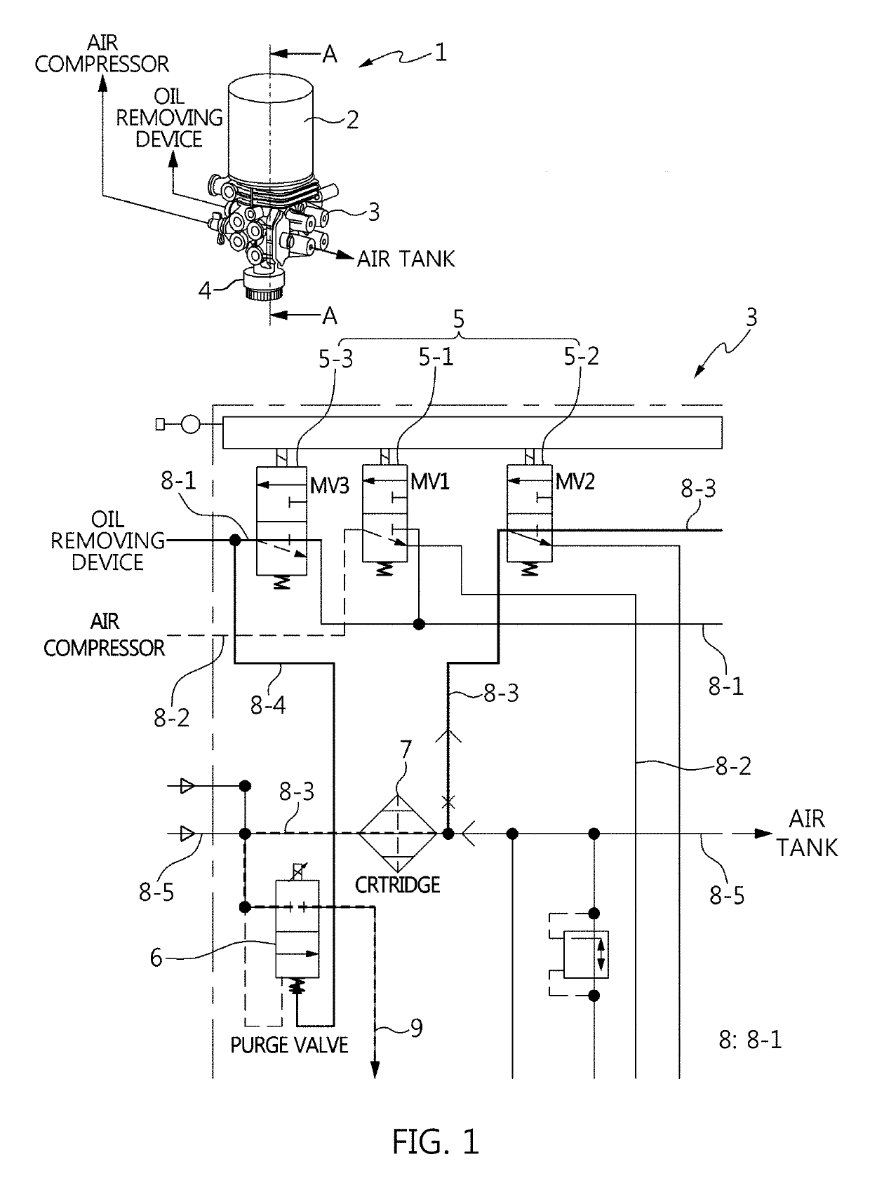
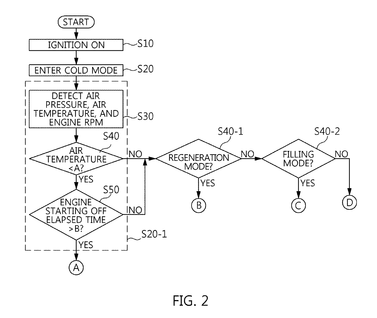
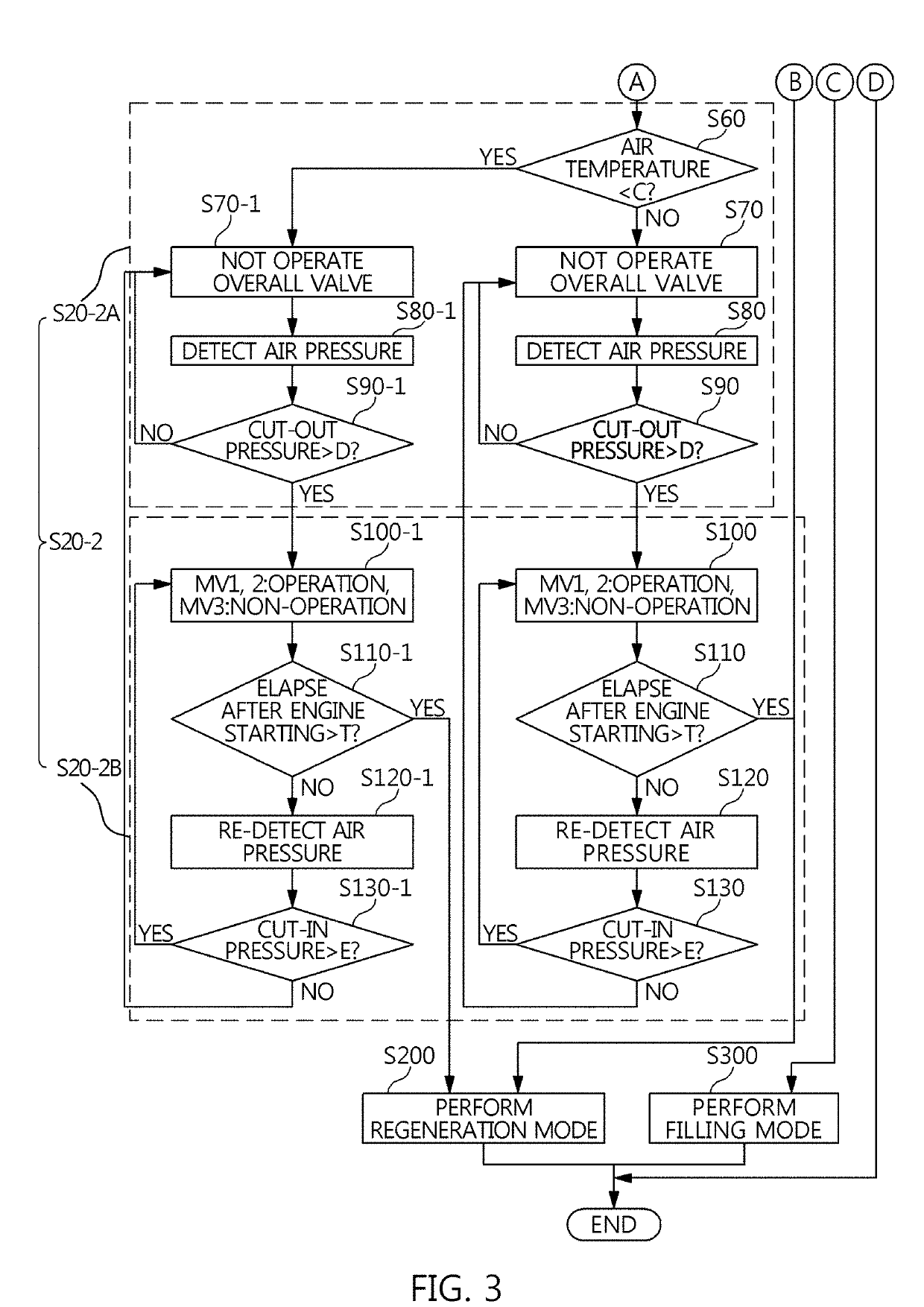
The present invention provides an air dryer control method using compressed air and a heaterless air dryer that can perform a new cold mode and a regeneration mode. The method includes a cold mode that controls the air temperature to freezing temperature and a purge valve to thaw the valve. The method also includes a regeneration mode that removes emulsion accumulated at the bottom of the cartridge by using the compressed air. The method can be implemented using a valve layout and a path switching valve to control the air flow. The invention provides an air dryer control method that improves the efficiency and performance of the air dryer in various conditions.

Problems solved by technology

In the instant case, the engine oil adversely affects a rubber product inside the air dryer to damage the rubber product, such that the life span of the expensive air dryer is lowered.
However, the air dryer cannot but have the following disadvantages due to the MV1 / MV2 valve and the heater.
First, in terms of the valve operation efficiency, the MV1 valve operation requires the unfilled mode conversion of the air compressor, the MV2 valve operation requires the simultaneous operation of the cartridge regeneration, the purge valve, and the oil removing device, and the MV1 valve operation is required for the MV2 valve operation since the MV2 valve cannot be controlled separately.
As the result, the valve cannot but lower the efficiency of the mode switching control of the air dryer.
Second, in terms of the heater starting efficiency, the operation of the purge valve before the complete thawing of the purge valve in winter may damage the rubber parts for airtightness, which may lead to air leakage and shortening the life span of the air dryer.
As the result, the heater cannot but lower the efficiency of the thawing control of the air dryer in winter.
Third, in terms of the cartridge regeneration efficiency, it is not possible to apply an effect of blowing out foreign matters, such as the emulsion accumulated in the lower portion of the cartridge of the air dryer, by the compressed air generated from the air compressor during the valve operation.

Method used


Image

  • Method of controlling air dryer using compressed air and heaterless air dryer thereof
  • Method of controlling air dryer using compressed air and heaterless air dryer thereof
  • Method of controlling air dryer using compressed air and heaterless air dryer thereof

Examples


Embodiment Construction

[0041]Reference will now be made in detail to various embodiments of the present invention(s), examples of which are illustrated in the accompanying drawings and described below. While the present invention(s) will be described in conjunction with exemplary embodiments of the present invention, it will be understood that the present description is not intended to limit the present invention(s) to those exemplary embodiments. On the other hand, the present invention(s) is / are intended to cover not only the exemplary embodiments of the present invention, but also various alternatives, modifications, equivalents and other embodiments, which may be included within the spirit and scope of the present invention as defined by the appended claims.

[0042]Hereinafter, embodiments of the present invention will be described in detail with reference to the accompanying drawings and these embodiments may be implemented in various forms by a person having ordinary skill in the art to which the pres...


PUM


Abstract

An air dryer control method may include a cold mode in which a controller performs a winter season condition control in which air temperature is lowered to freezing temperature if an engine starting is detected, and performs a winter season thawing control in which compressed air introduced into a valve control of an air dryer warms a purge valve of the air dryer.

Description

CROSS-REFERENCE TO RELATED APPLICATION[0001]The present application claims priority to Korean Patent Application No. 10-2018-0033438, filed on Mar. 22, 2018, the entire contents of which is incorporated herein for all purposes by this reference.BACKGROUND OF THE INVENTIONField of the Invention[0002]The present invention relates to an air dryer for a vehicle, and more particularly, to a heaterless air dryer configured for controlling an air dryer using compressed air for raising an internal temperature of the air dryer without a separate heating element.Description of Related Art[0003]Generally, a commercial vehicle has an air management system for generating and using compressed air used as an energy source, in which the air management system has an air dryer as a main component.[0004]For example, the air management system may include an air compressor for generating compressed air, an oil removing device configured for removing foreign matters (oil, moisture) coming from the air co...

Claims


Application Information

Patent Timeline
IPC IPC(8): B60T17/02B60T17/00F15B21/04B01D53/04
CPCF15B21/048B01D2259/4566B01D53/261B01D53/0454F04B39/16B60T17/006B60T17/004B60T17/02B01D53/26B01D2257/80F15B2211/8855F15B2211/85F15B21/041F15B2211/66F15B2211/6309F15B2211/6343F15B2211/6336F15B21/04F15B21/045F15B2211/6658F15B21/0427
Inventor CHUN, JONG-CHUL
Owner HYUNDAI MOTOR CO LTD
Learn More