
Evaporative cooling system

Active Publication Date: 2019-09-26
LENOVO (BEIJING) CO LTD
View PDF0 Cites 3 Cited by
  • Summary
  • Abstract
  • Description
  • Claims
  • Application Information

AI Technical Summary

Benefits of technology

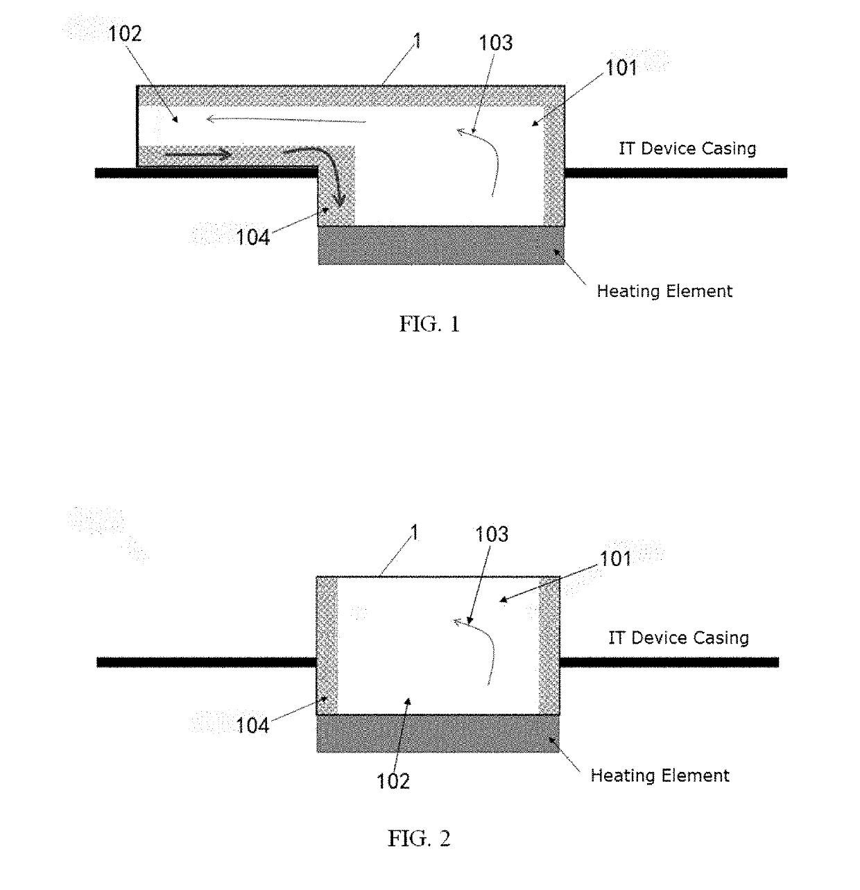
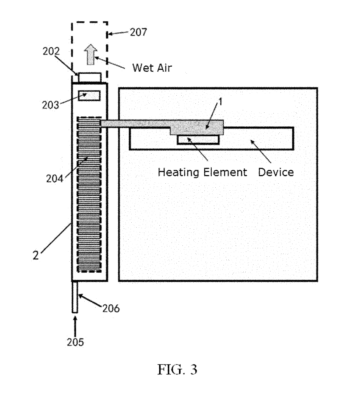
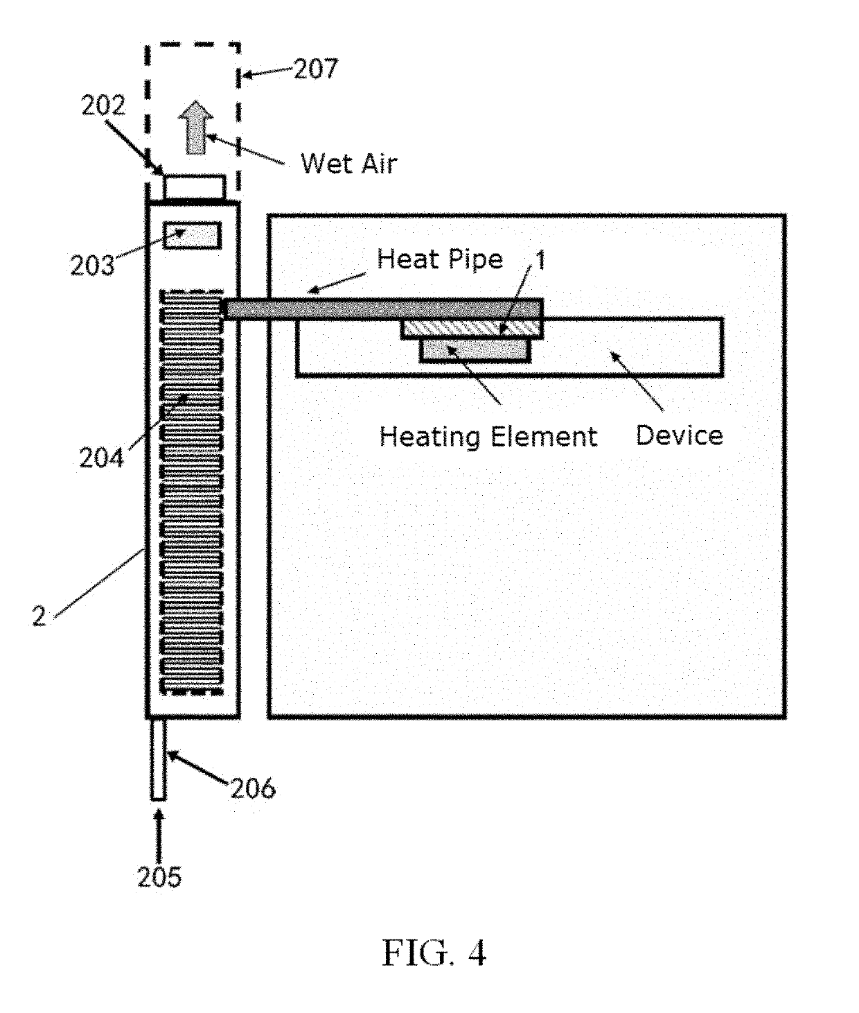
The present patent describes an evaporative cooling system for data centers that improves energy efficiency and simplifies the cooling process. It consists of a heat conducting device, a heat dissipating device, and an evaporator. The system increases heat dissipation efficiency, reduces energy consumption and noise, and eliminates complex pipe and outdoor equipment designs. Additionally, the system allows for the water in the server room to be at room temperature, thereby avoiding the need for controlling the inlet water temperature and improving safety. Overall, this system provides a more efficient, simplified, and safe solution for cooling data centers.

Problems solved by technology

With the increase in dissipated energy density and global energy shortage, low energy efficiency has become a pain point of data centers.
This type of cooling requires complex piping and outdoor equipment design.
However, liquid cooling solutions usually involve complex piping designs and have high requirements for data center infrastructure, hence implementing or expanding the liquid cooling solution becomes more difficult with higher risks for existing data centers.
Further, conventional liquid cooling solutions also require heat to be exchanged from the data center to the outside world using large and complex outdoor equipment that are expensive to purchase and operate.
Furthermore, limited heat emission space and noise restrictions also make the liquid cooling solution difficult to implement.
In addition to the challenges set forth above, the conventional water-cooled door method also faces challenges such as requiring low temperature inlet water and high-speed fans.
This increases energy consumption and requires additional support equipment such as water cooling machines.
Further, the cooling inside the rack is still done using air cooling, which requires the use of high-speed fans to perform heat exchange between the hot air and the water-cooled door, and the high-speed fans have low cooling efficiency.

Method used


Image

  • Evaporative cooling system
  • Evaporative cooling system
  • Evaporative cooling system

Examples


Embodiment Construction

[0031]Hereinafter, aspects, features, and embodiments of the present disclosure will be described with reference to the accompanying drawings. It should be understood that such description is exemplary only but is not intended to limit the scope of the present disclosure. In addition, it will be understood by those skilled in the art that various modifications in form and details may be made therein without departing from the spirit and scope of the present disclosure.

[0032]Features and aspects of the present disclosure will become apparent with reference to the accompanying drawings and non-limiting examples describing various preferred embodiments of the present disclosure.

[0033]It will also be appreciated that although the present disclosure has been described with reference to some specific examples, equivalents of the present disclosure can be achieved by those skilled in the art. These equivalents having features claimed in the present disclosure should fall within the scope o...


PUM


Abstract

An evaporative cooling system having a heat conducting device, the heat conducting device being capable of coupling to a heating element to be cooled and the heat conducting device comprising a first medium; a heat dissipating device having one or more heat dissipating outlets; and an evaporator disposed in the heat dissipating device and arranged in relation to the heat conducting device that is arranged at least partially outside the heat dissipating device. The heat dissipating device comprises a second medium, and the evaporator is configured to receive heat from the heat conducting device to heat the second medium of the heat dissipating device and discharge the heat from the one or more heat dissipating outlets of the heat dissipating device.

Description

CROSS-REFERENCES TO RELATED APPLICATIONS[0001]This application claims the priority to Chinese Patent Application No. 201810230445.7, entitled “Evaporative Cooling System,” filed on Mar. 20, 2018, the entire content of which is incorporated herein by reference.FIELD OF TECHNOLOGY[0002]The present disclosure relates to the field of thermal management. More specifically, the present disclosure relates to an evaporative cooling system.BACKGROUND[0003]With the increase in dissipated energy density and global energy shortage, low energy efficiency has become a pain point of data centers. Statistically, energy used for server cooling accounts for half of the energy consumption of traditional data centers, and some are even higher.[0004]Currently, the well-adopted server room cooling methods include the conventional server room water cooling method and the conventional water-cooled door method.[0005]The conventional server room water cooling method often includes two liquid circulations. In...

Claims


Application Information

Patent Timeline
IPC IPC(8): F28D15/02F25B39/02
CPCF25B39/022F28D15/0233H05K7/20809F25B23/006H05K7/20827F28D15/0275H01L23/427
Inventor TIAN, TINGZHANG, LIANPEI
Owner LENOVO (BEIJING) CO LTD
Learn More