Automatic motor lead wire cutting and twisting assembly

a technology of lead wire cutting and twisting, which is applied in the manufacture of dynamo-electric machines, dynamo-electric machines, electrical apparatus, etc., can solve the problems of complex operation, low efficiency, and enormous labor, and achieve the effect of preventing vibration of the workpi

Inactive Publication Date: 2019-09-26
DONGGUAN UNIV OF TECH
View PDF0 Cites 15 Cited by
  • Summary
  • Abstract
  • Description
  • Claims
  • Application Information

AI Technical Summary

Benefits of technology

[0020]With the design of wire twisting and securing mechanism, the securing lifting cylinder may press the securing head downward to finish securing process to prevent vibration of the work piece during the wire twisting process.

Problems solved by technology

The deficiencies of the prior art may include complex operation, low efficiency and enormous labor due to shortness of the wire and manual operation.

Method used


Image

  • Automatic motor lead wire cutting and twisting assembly
  • Automatic motor lead wire cutting and twisting assembly
  • Automatic motor lead wire cutting and twisting assembly

Examples


Embodiment Construction

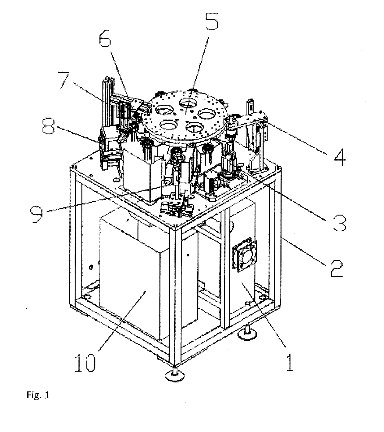
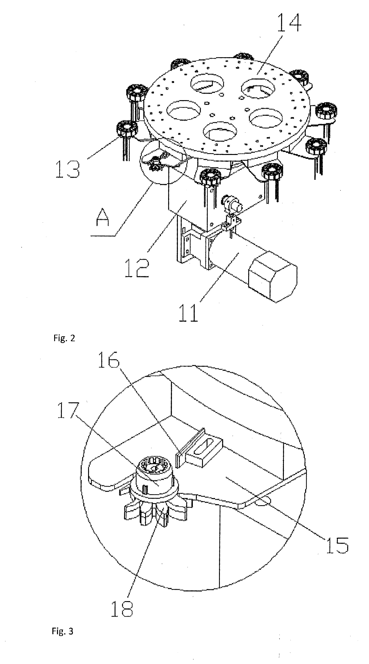
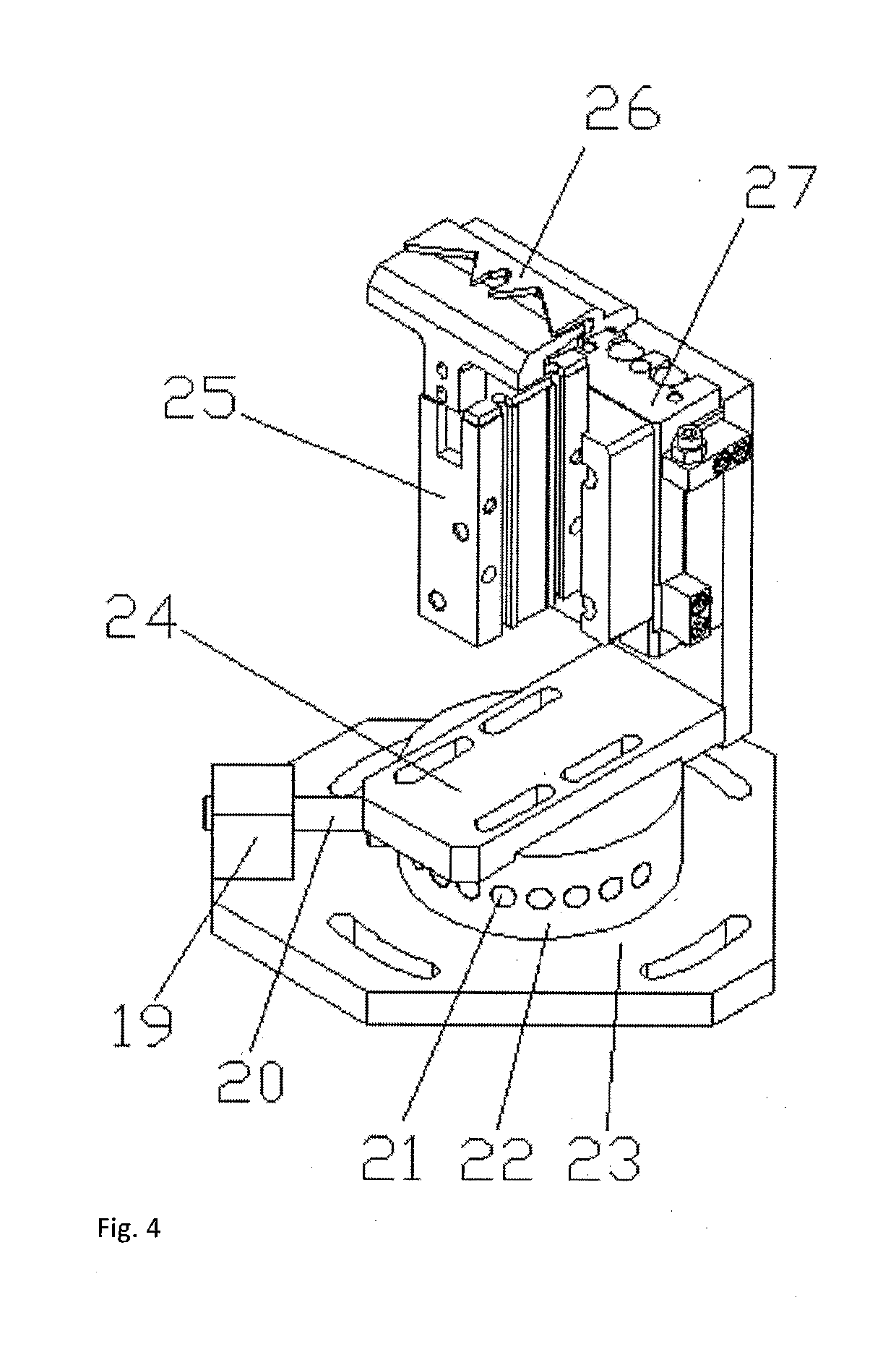
[0030]All of the various elements in the figures are shown as follows:[0031]1. power control box,[0032]2. rack,[0033]3. wire twisting mechanism,[0034]4. wire twisting and securing mechanism,[0035]5. turntable mechanism,[0036]6. wire collating mechanism,[0037]7. wire teasing mechanism,[0038]8, wide cutting mechanism,[0039]9. single cutting mechanism,[0040]10. reject tank,[0041]11. servo drive motor,[0042]12. gear box,[0043]13. component,[0044]14. disk,[0045]15. clamping plate,[0046]16. positioning block,[0047]17. central clamp,[0048]18. wire separation claw,[0049]19. spring block,[0050]20. positioning pin roll,[0051]21. positioning hole,[0052]22. rotation base,[0053]23. wire collating base plate,[0054]24. adjusting board,[0055]25. pneumatic claw,[0056]26. wire combing claw,[0057]27. first sliding table cylinder,[0058]28. vertical securing plate,[0059]29. securing head,[0060]30. securing lifting cylinder,[0061]31. upper transverse securing plates,[0062]32. wire teasing rack,[0063]33. ...


PUM

PropertyMeasurementUnit
lengthaaaaaaaaaa
stabilityaaaaaaaaaa
combing angleaaaaaaaaaa

Abstract

The present invention relates to an automatic motor lead wire cutting and twisting assembly which may include a rack, a turntable mechanism and a power control box which are both provided on the rack. On the rack surrounding the turntable mechanism are in turn provided a wire collating mechanism, a wire teasing mechanism, a wide cutting mechanism, a single cutting mechanism and a wire twisting mechanism. A wire teasing and securing mechanism is provided on the rack above the wire twisting mechanism. A reject tank is provided on the rack below the wide cutting mechanism and the single cutting mechanism. All of the drive components of the above mechanisms are electrically connected to the power control box. Cooperating with motor production equipment, an automated production line is formed, which mainly comprises turntable mechanism, wire collating mechanism, wire cutting part, and twisting part etc., with delicate structural design, high automation level, and time and human resource saving compared to manual operation, and conduces to improve production efficiency of motor production lines.

Description

FIELD OF THE INVENTION[0001]The present invention relates generally to the production equipment for motors, and more particularly to an automatic motor lead wire cutting and twisting assembly.BACKGROUND OF THE INVENTION[0002]A kind of motor lead wire is needed in the motor production technical field: the lead wire is less than 5 centimeter long and the both ends of the lead wire are covered with a layer of tin. In the prior art, the production of such kind of lead wire is mostly done with manual operation: cut the lead wire into a desired length, twist the lead wire and the twisted end of the wire may be processed by tin immersion. The deficiencies of the prior art may include complex operation, low efficiency and enormous labor due to shortness of the wire and manual operation.SUMMARY OF THE INVENTION[0003]The present invention discloses an automatic motor lead wire cutting and twisting assembly. While working with the motor production equipment to form the automated assembly line,...

Claims


Application Information

Patent Timeline
Patent Type & Authority Applications(United States)
IPC IPC(8): H02K15/00B21F11/00B21F15/04
CPCB21F15/04H02K15/0087B21F11/00H02K15/0068Y10T29/49071Y10T29/53157Y10T29/53143
Inventor QIANG, MIAO
Owner DONGGUAN UNIV OF TECH
Why Eureka
Try Eureka