
Substrate processing method

a substrate and processing method technology, applied in the direction of coatings, metallic material coating processes, chemical vapor deposition coatings, etc., can solve the problems of affecting the yield management of the manufacturing process, the characteristics of the thin film and the device may become positionally non-uniform, and the damage to the sublayer in the plasma process, so as to increase the radical density of the reactant

Active Publication Date: 2019-10-03
ASM IP HLDG BV
View PDF0 Cites 247 Cited by
  • Summary
  • Abstract
  • Description
  • Claims
  • Application Information

AI Technical Summary

Benefits of technology

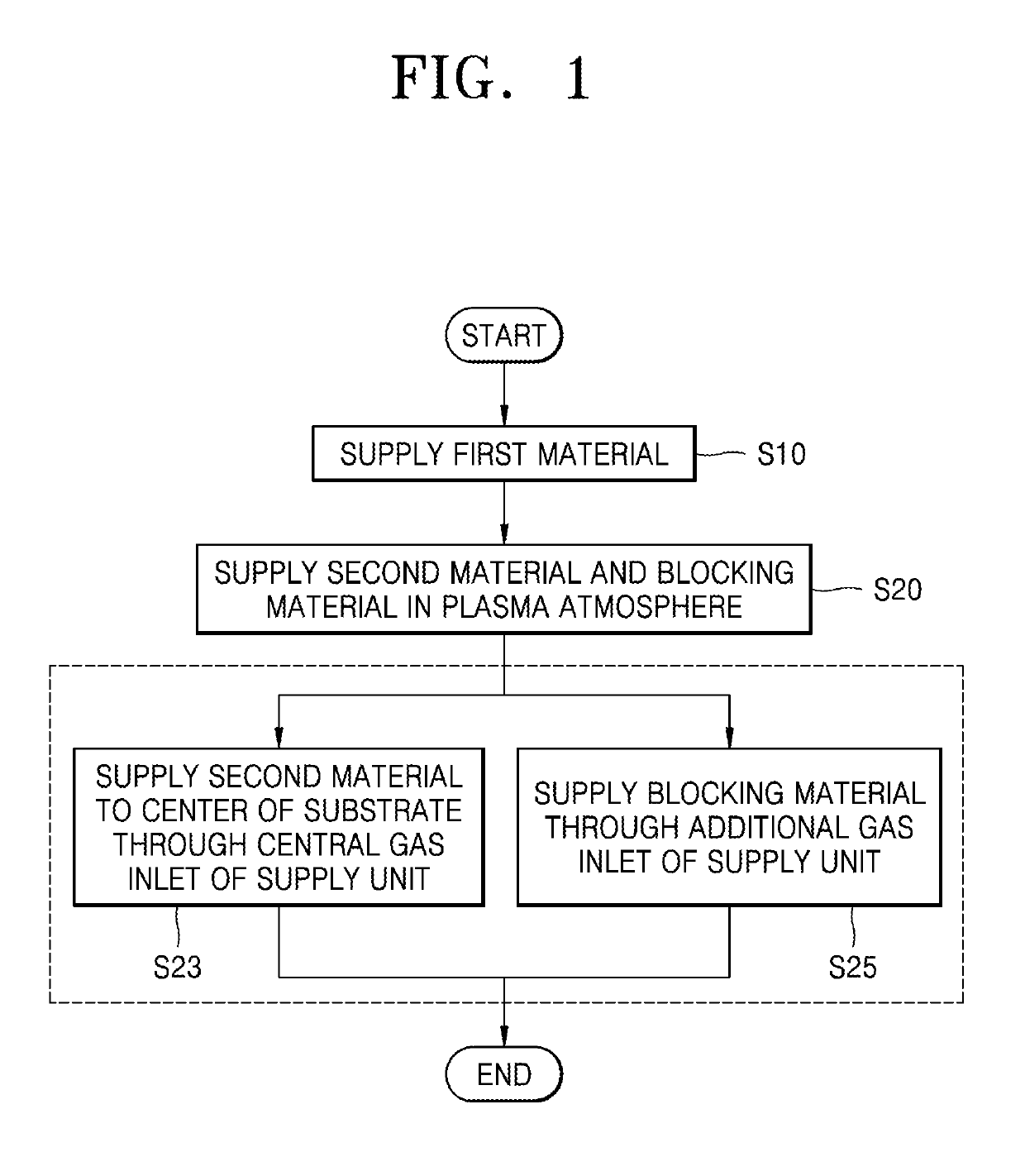
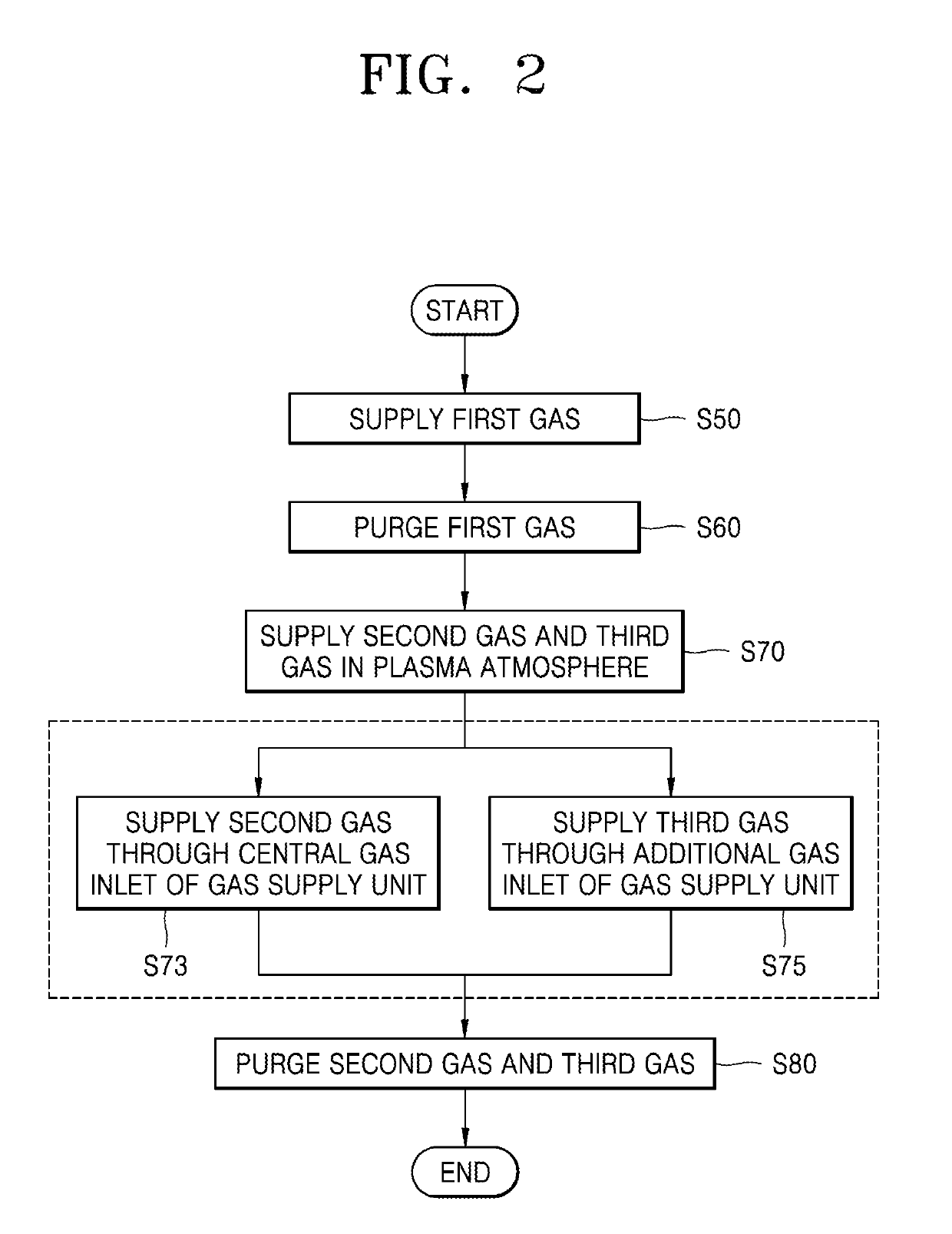
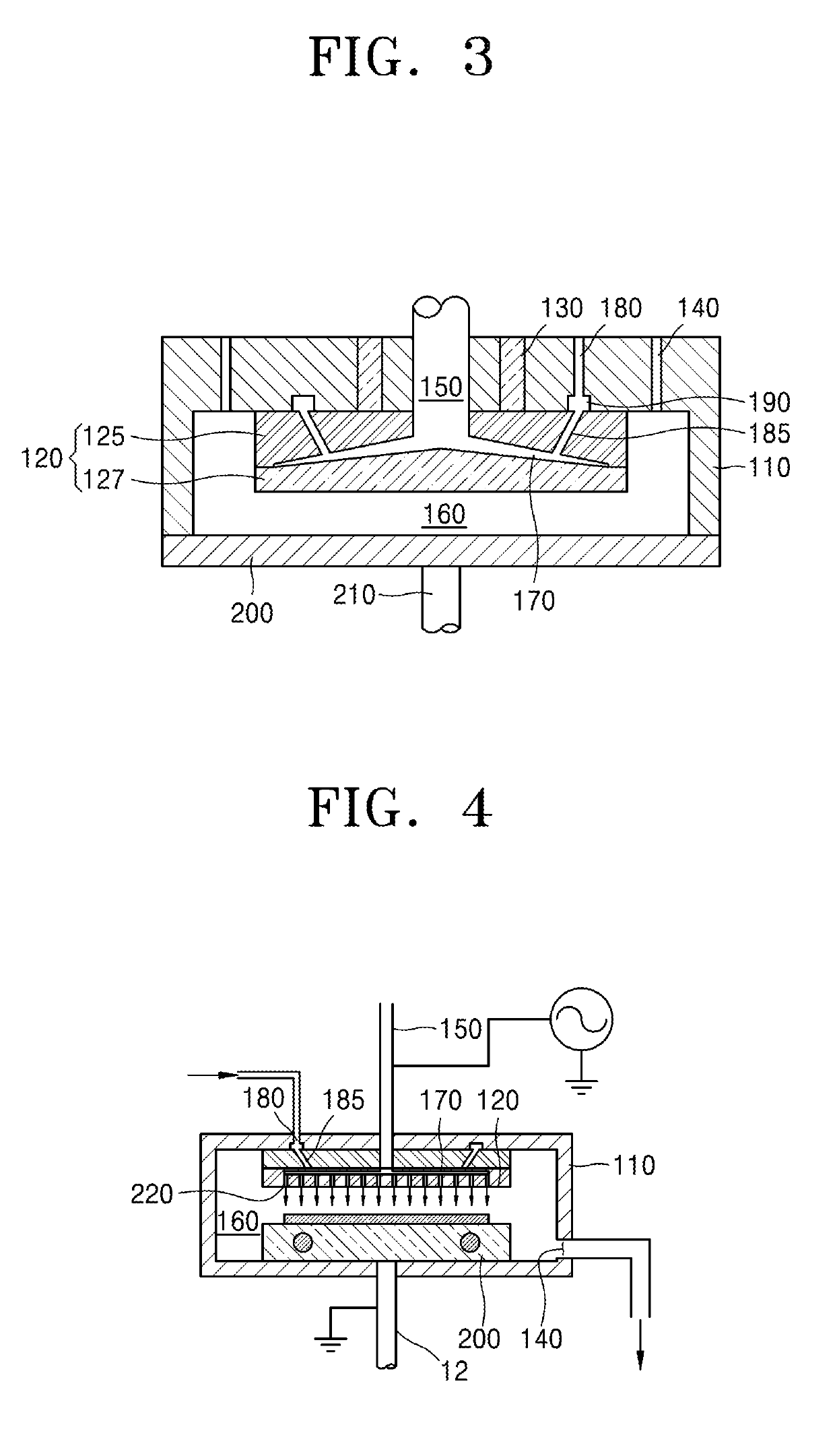
The patent describes a method for processing a substrate by supplying a source material and a reactant to the substrate in a plasma atmosphere. The method includes adding an additional gas inlet to increase the flow of a blocking material at the edge of the substrate, which reduces the density of a reactive species near the center of the substrate and increases the radical density near the edge. This results in uniform damage to the pattern structure on the substrate. Overall, the method improves the patterning accuracy and reliability of the substrate processing.

Problems solved by technology

In particular, damage to a sublayer occurs in a plasma process due to active radicals.
Due to the non-uniformity of the damage, the characteristics of the thin film and the device may become positionally non-uniform.
That is, when damage uniformity is low as a whole, yield management of the manufacturing process is negatively affected.
Damage to the pattern structure may occur in the plasma atmosphere.
The nitrogen-containing gas may be supplied through the additional gas inlet to increase a flow at an edge of the substrate, due to the increased flow of nitrogen-containing gas at the edge of the substrate, a density of a radical that is reactive with the pattern structure at the edge of the substrate may be reduced, and due to the increased flow of nitrogen-containing gas at the edge of the substrate, the density of a radical that is reactive with the pattern structure at a center of the substrate may be increased, and as a result, damage to the pattern structure at the edge of the substrate and damage to the pattern structure near the center of the substrate may become uniform.

Method used


Image

  • Substrate processing method
  • Substrate processing method
  • Substrate processing method

Examples


Embodiment Construction

[0034]Reference will now be made in detail to embodiments, examples of which are illustrated in the accompanying drawings, wherein like reference numerals refer to like elements throughout. In this regard, the present embodiments may have different forms and should not be construed as being limited to the descriptions set forth herein. Accordingly, the embodiments are merely described below, by referring to the figures, to explain aspects of the present description. As used herein, the term “and / or” includes any and all combinations of one or more of the associated listed items. Expressions such as “at least one of,” when preceding a list of elements, modify the entire list of elements and do not modify the individual elements of the list.

[0035]The terminology used herein is for the purpose of describing particular embodiments and is not intended to limit the present disclosure. As used herein, the singular forms “a”, “an”, and “the” are intended to include the plural forms as well,...


PUM

PropertyMeasurementUnit
temperatureaaaaaaaaaa
frequencyaaaaaaaaaa
temperatureaaaaaaaaaa

Abstract

A substrate processing method capable of uniformly maintaining damage to a pattern structure under a thin film formed on a substrate includes supplying a source material to a substrate on which a pattern structure that is reactive with a reactant is formed; and supplying the reactant through at least a central gas inlet of a supply unit in a plasma atmosphere, wherein, during the supplying of the reactant, a blocking material different from the reactant is supplied through an additional gas inlet that is spaced apart from the central gas inlet of the supply unit, and a flow of the blocking material at the edge of the substrate is increased, thereby increasing a radical density of the reactant near a center of the substrate.

Description

CROSS-REFERENCE TO RELATED APPLICATION[0001]This application claims the benefit of Korean Patent Application No. 10-2018-0037762, filed on Mar. 30, 2018, in the Korean Intellectual Property Office, the disclosure of which is incorporated herein in its entirety by reference.BACKGROUND1. Field[0002]One or more embodiments relate to a substrate processing method, and more particularly, to a substrate processing method capable of improving the characteristics of a thin film layer.2. Description of the Related Art[0003]In a substrate processing process of depositing and etching a thin film on a substrate, it is important to keep the uniformity of each portion of the substrate constant in order to increase the yield of a semiconductor device in manufacturing process. In particular, damage to a sublayer occurs in a plasma process due to active radicals. In some cases, the degree of damage varies depending on each portion of the substrate. Due to the non-uniformity of the damage, the charac...

Claims


Application Information

Patent Timeline
Patent Type & Authority Applications(United States)
IPC IPC(8): H01L21/02C23C16/04C23C16/40C23C16/50H01L21/311H01L21/033
CPCH01L21/02274C23C16/50H01L21/02164C23C16/042H01L21/31111C23C16/402H01L21/0337H01L21/0228C23C16/513C23C16/52C23C16/45525C23C16/45542C23C16/45534C23C16/45565C23C16/45544C23C16/04C23C16/45502C23C16/45574H01L21/0262H01L21/324H01L21/02312
Inventor CHOI, SEUNG WOO
Owner ASM IP HLDG BV
Learn More