Light source device

a light source and device technology, applied in the direction of instruments, semiconductor lasers, diffusing elements, etc., can solve the problems of failure of external resonance, large deviation of light beam, and large length of the external cavity of the light source device with the above structur

Active Publication Date: 2019-10-03
NICHIA CORP
View PDF0 Cites 11 Cited by
  • Summary
  • Abstract
  • Description
  • Claims
  • Application Information

AI Technical Summary

Benefits of technology

[0005]One object of the present invention is to provide a light source device in which the external cavity length can be shortened.
[0009]According to certain embodiments, a light source device having a short external cavity length can be provided.

Problems solved by technology

However, the light source device with the above structure has a great external cavity length between the laser source and the partially reflecting mirror.
With a great external cavity length, even a slight deviation in position of an optical element constituting the external cavity due to vibration causes a great deviation of the light beam.
This may result in a failure of external resonance, and thus the WBC device may not work.

Method used


Image

  • Light source device
  • Light source device
  • Light source device

Examples


first embodiment

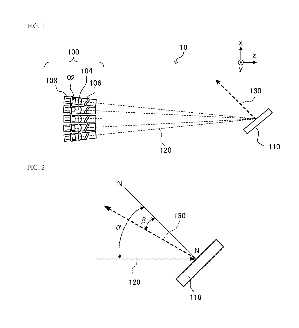
[0020]FIG. 1 is a schematic view of a light source device according to a first embodiment of the present invention. A light source device 10 of the present embodiment includes a plurality of external cavity modules 100 and a combining grating 110. Each of the external cavity modules 100 includes a laser source 102, a collimating part 104, a plane transmission grating 106, and a stage 108. In each external cavity module 100, the laser source 102, the collimating part 104, and the plane transmission grating 106 are disposed at the same stage 108, so that the external cavity module 100 can be moved integrally. In this case, the laser source 102 is preferably disposed in contact with the stage 108 to allow the laser source 102 to be cooled by cooling the stage 108.

[0021]An x axis, a y axis, and a z axis, which are orthogonal to one another, are shown in FIG. 1 for the convenience of description. In FIG. 1, light beams are schematically represented in dashed lines and denoted as light be...

second embodiment

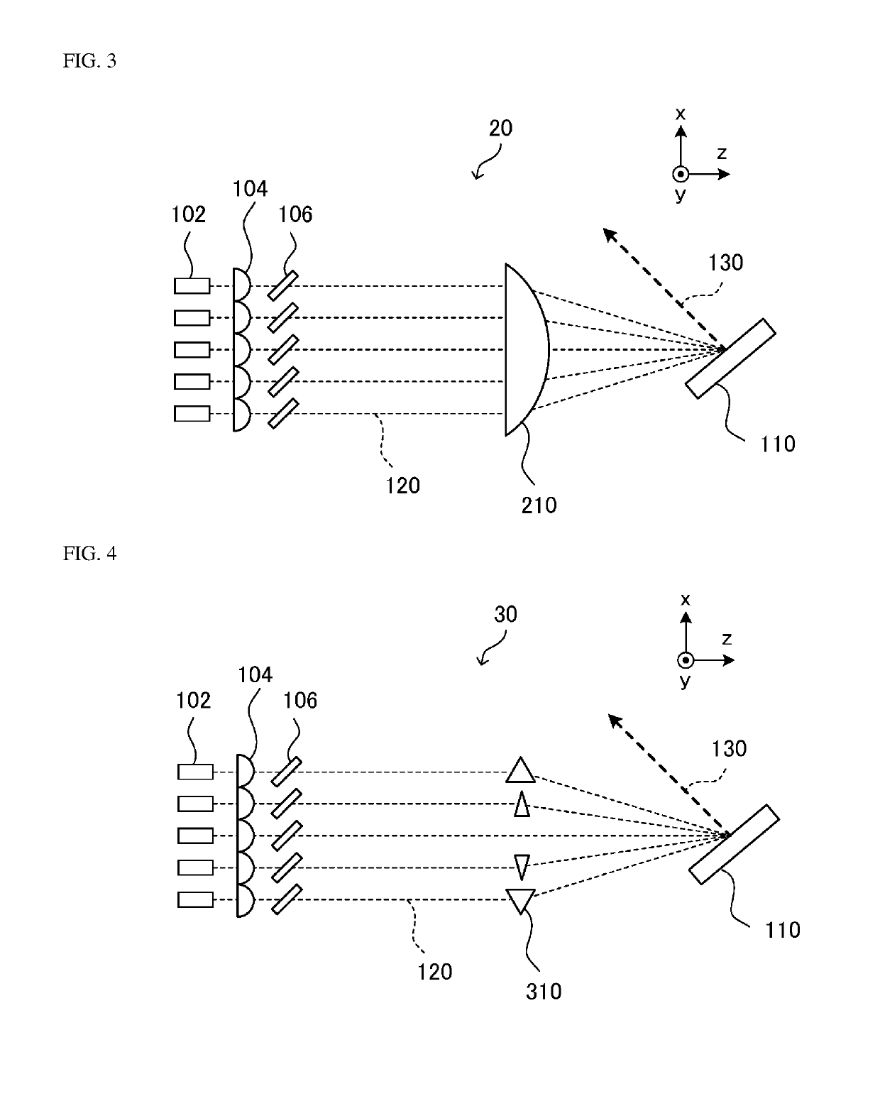
[0036]FIG. 3 is a schematic view of a light source device according to a second embodiment of the present invention. A light source device 20 in the present embodiment is a modification of the light source device 10. In the present embodiment, members, portions, components, and elements having the same functions as the first embodiment are denoted by the same reference numerals as those in the first embodiment, and duplicative description thereof may be omitted.

[0037]The light source device 20 includes a plurality of laser sources 102 as in the light source device 10. Each of the laser sources 102 includes a collimating part 104 and a plane transmission grating 106. The plane transmission grating 106 is configured to diffract a portion of light emitted from the corresponding laser source 102 back to the laser source 102 to cause external resonance between the laser source 102 and the plane transmission grating 106. That is, the laser source 102, the collimating part 104, and the pla...

third embodiment

[0040]FIG. 4 is a schematic view of a light source device according to a third embodiment of the present invention. A light source device 30 in the present embodiment is a modification of the light source device 20 in the second embodiment. In the present embodiment, members, portions, components, and elements having the same functions as those in the second embodiment are denoted by the same reference numerals as the second embodiment, and duplicative description thereof may be omitted.

[0041]The light source device 30 is different from the light source device 20 mainly in that prisms 310 are used instead of a deflector-condenser lens 210. As shown in FIG. 4, five external cavities are provided in the light source device 30, and prisms 310 are disposed each corresponding to a corresponding one of external cavities other than the external cavity at the center. The incident angle of light beam 120 emitted from the external cavity and entering a combining grating 110 is defined by the ...


PUM


Abstract

A light source device includes: a plurality of laser sources; a plurality of collimating parts, each configured to collimate the light beam emitted from a corresponding one of the laser sources; a combining grating configured to diffract, at an identical diffraction angle, light beams that have passed through the collimating parts and are incident on the combining grating at different incident angles, to combine the diffracted light beams; and a plurality of plane transmission gratings, wherein each of the plane transmission gratings is disposed in an optical path between a corresponding one of the collimating parts and the combining grating, and wherein each of the plane transmission gratings is adjustable so as to allow selection of a wavelength of the light beam incident on the combining grating.

Description

CROSS-REFERENCE TO RELATED APPLICATION[0001]This application claims priority to Japanese Patent Application No. 2018-061647, filed on Mar. 28, 2018, the contents of which are hereby incorporated by reference in their entirety.BACKGROUND OF THE INVENTION1. Field of the Invention[0002]The present disclosure relates to a light source device that applies wavelength beam combining (WBC) to emit high-output laser light.2. Description of Related Art[0003]Demand for light source devices to emit high-output laser light has increased in various fields including laser processing such as laser soldering. One example of light source devices to emit high-output laser light is a wavelength beam combining device (hereinafter referred to as a “WBC device”). U.S. Pat. No. 6,192,062 describes an example of a WBC device. The WBC device described in U.S. Pat. No. 6,192,062 includes: a light source unit, such as a laser diode (LD) bar, in which a plurality of laser sources (for example, LDs) are arranged...

Claims


Application Information

Patent Timeline
Patent Type & Authority Applications(United States)
IPC IPC(8): H01S5/14G02B27/10G02B5/18G02B5/02H01S5/40
CPCG02B27/1086H01S5/02212H01S5/141H01S5/4012G02B5/0278G02B5/1866H01S5/4087
Inventor DEJIMA, NORIHIROOMORI, MASAKI
Owner NICHIA CORP
Why Eureka
Try Eureka