Fiber laser convenient to generate high repetition frequency pulse laser light

A fiber laser, high repetition rate technology, applied in the direction of lasers, laser components, phonon exciters, etc., can solve the problems that the full polarization-maintaining system cannot be fully utilized, and there is no application of polarization-maintaining fiber, and achieves simple structure and lock Unique mold point, anti-instability effect

Pending Publication Date: 2018-11-02
广东华奕激光技术有限公司
View PDF4 Cites 2 Cited by
  • Summary
  • Abstract
  • Description
  • Claims
  • Application Information

AI Technical Summary

Problems solved by technology

However, saturable absorbers such as semiconductor saturable absorbers (SESAM), carbon nanotube saturable absorbers, graphene saturable absorbers, etc. have the disadvantages of low damage threshold and decay with time, which limit their development Laboratory, to a broader industrial market
On the other hand, the fiber laser technology using the nonlinear rotating polarization effect (NPE) cannot fully utilize the full polarization-maintaining system. Without the application of polarization-maintaining fiber, the NPE technology is easily disturbed by the environment

Method used


Image

  • Fiber laser convenient to generate high repetition frequency pulse laser light
  • Fiber laser convenient to generate high repetition frequency pulse laser light

Examples


Embodiment 1

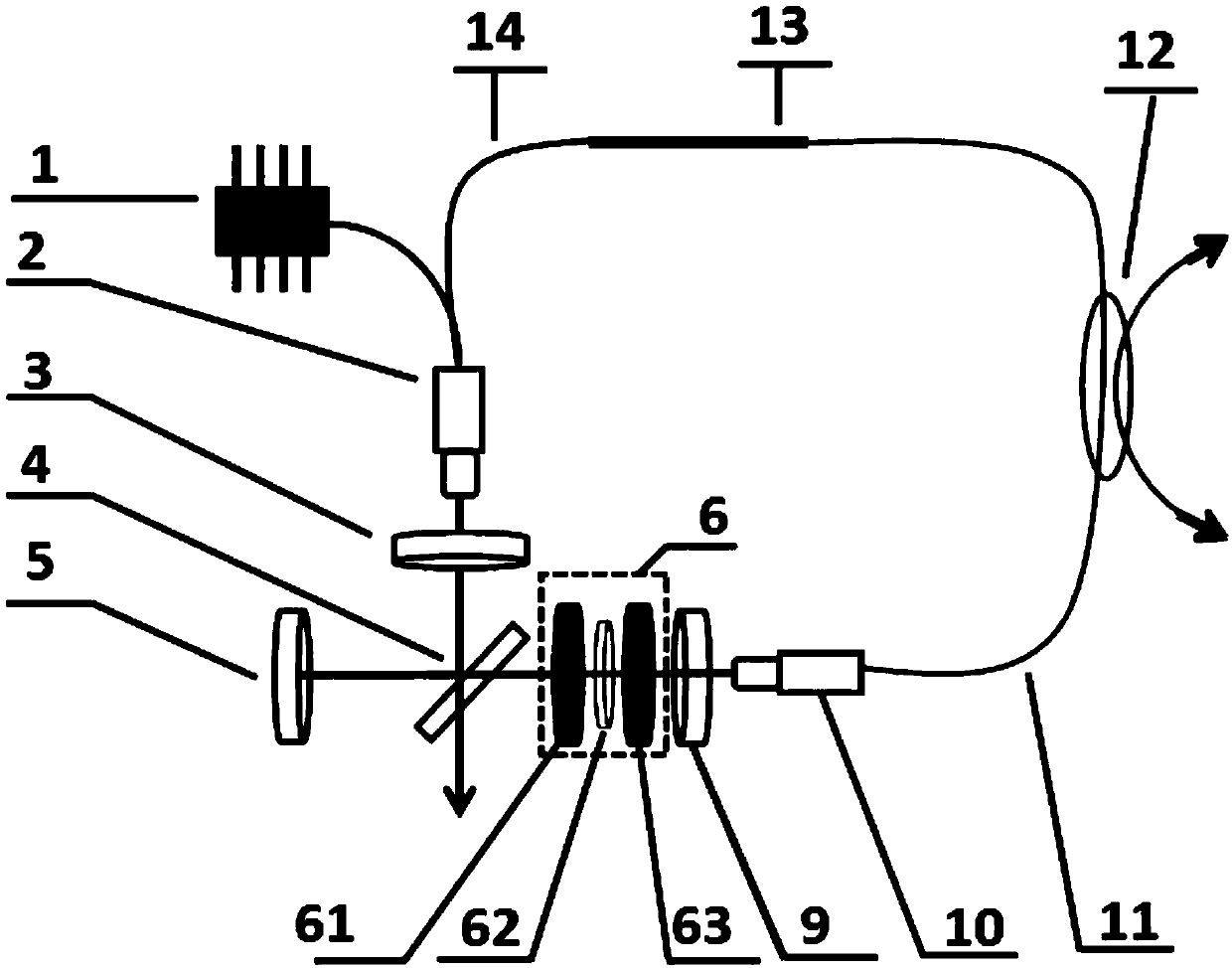
[0027] Example 1, such as figure 1 As shown, during specific implementation, the phase shifter unit 6 adopts a linear phase shifter, which includes a first Faraday rotator 61, a 1 / 4 wave plate 62, and a second Faraday rotator 63. The first Faraday rotator Mirror 5, first beam splitter 4, first Faraday rotator 61, 1 / 4 wave plate 62, second Faraday rotator 63, second 1 / 2 wave plate 9, second fiber collimator 10 The straight outlets are arranged in a straight line in turn.

[0028] As mentioned above, during specific implementation, the first wavelength division multiplexing collimation unit 2 adopts a wavelength division multiplexing collimator.

[0029] As mentioned above, during operation, the first pumping source 1 couples the pumping light into the cavity through the first wavelength division multiplexing collimation unit 2, and by increasing the pumping power above the threshold of the fiber laser, the laser Oscillation occurs; the polarization state output by the first w...

Embodiment 2

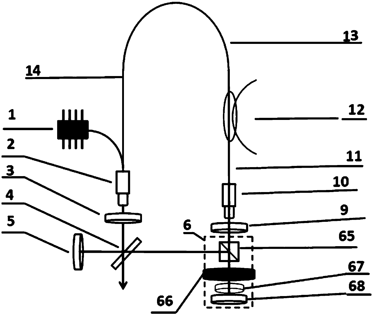
[0033] Example 2, such as figure 2 As shown, during specific implementation, the phase shifter unit 6 adopts a reflective phase shifter, which includes a polarization beam splitter cube 65, a third Faraday rotator 66, a 1 / 8 wave plate 67, and a second mirror 68 , the first reflector 5, the first beam splitter 4, and the polarization beam splitter cube 65 are arranged linearly in sequence, and the second reflector 68, the 1 / 8 wave plate 67, the third Faraday rotator 66, the polarization beam splitter The cube 65, the second 1 / 2 wave plate 9, and the collimated output ends of the second fiber collimator 10 are arranged in a straight line in sequence.

[0034] As mentioned above, during specific implementation, the first wavelength division multiplexing collimation unit 2 adopts a wavelength division multiplexing collimator.

[0035] As mentioned above, during operation, the first pumping source 1 couples the pumping light into the cavity through the first wavelength division m...


PUM


Abstract

The invention discloses a fiber laser convenient to generate high repetition frequency pulse laser light. A nonlinear loop mirror is adopted for polarization-maintaining mode locking; the mode lockingmechanism has the characteristics of being unique in mode locking point, not easy to unlock, free of an easy-to-wear device and broad in mode locking spectrum in comparison with traditional mode locking methods, such as an SESAM or an NPR, and is an ideal next generation fiber femtosecond laser seed source. By adopting a phase offset technology for built-in space, the fiber laser has the characteristics of being simple in structure and low in mode locking threshold in comparison with a traditional 8-shaped mode locking laser; the power requirement on an LD is reduced; and meanwhile, the service life of a whole device is prolonged. Furthermore, a negative dispersion single mode fiber and a positive dispersion fiber are also adopted for controlling dispersion, and addition of extra spatialdiscrete devices, such as a grating or a prism pair is avoided, so that the overall reliability is greatly enhanced.

Description

technical field [0001] The present invention relates to a fiber laser which is convenient for generating high repetition frequency pulsed laser light. Background technique [0002] Driven by fields such as spectroscopy, nonlinear optical imaging, and other research fields, the demand for ultrafast lasers has expanded in recent years. Especially in the rapidly growing industrial high-end micro-processing market in recent years, the demand for high-end picosecond and femtosecond lasers continues to grow. The 1.5um band has great uses in human eye safety and OCT. The use of fiber technology to replace the solid seed source technology itself has many advantages, and the use of full polarization-maintaining fiber lasers in fiber technology is considered to be an effective method that can resist environmental changes. [0003] At present, the commonly used technology is to use saturable absorber mode-locking technology to make fully polarization-maintaining fiber lasers. Howeve...

Claims


Application Information

Patent Timeline
Patent Type & Authority Applications(China)
IPC IPC(8): H01S3/067H01S3/098
CPCH01S3/06712H01S3/06725H01S3/1106
Inventor 张志刚朱海波梁崇智
Owner 广东华奕激光技术有限公司
Why Eureka
Try Eureka