
System and method for power delivery

a power receiver and power supply technology, applied in the field of charging, can solve the problems of short battery life, difficult to address, and difficult to deliver power and storag

Inactive Publication Date: 2019-10-10
RGT UNIV OF MICHIGAN
View PDF0 Cites 9 Cited by
  • Summary
  • Abstract
  • Description
  • Claims
  • Application Information

AI Technical Summary

Benefits of technology

The patent text describes a system and method to improve the availability and accessibility of charging services for electric vehicles. The system aims to address issues such as low battery capacity, slow re-charging rates, and the limited availability of charging services. It offers an intelligent charging service with functions like automatic management, positioning, tracking, and recording. The system also provides information about the source of power, carbon footprint, and performance of the electric vehicle. The technical effects of the invention include enhanced charging experiences, increased access to charging services, and reduced burden on off-power grid charging.

Problems solved by technology

With the size of electronic circuits shrinking, power delivery and storage are becoming more challenging.
However, short battery life has severely restricted the range of electric powered UAVs and has proven difficult to address.
Conventional systems have attempted to employ solar power, hybrid propulsion (onboard fuel-powered generators), and hydrogen fuel cells to extend UAVs' operation time; however these have not provided more than a few additional hours of operation.

Method used


Image

  • System and method for power delivery
  • System and method for power delivery
  • System and method for power delivery

Examples


Embodiment Construction

[0029]Example embodiments will now be described more fully with reference to the accompanying drawings.

[0030]Example embodiments are provided so that this disclosure will be thorough, and will fully convey the scope to those who are skilled in the art. Numerous specific details are set forth such as examples of specific components, devices, and methods, to provide a thorough understanding of embodiments of the present disclosure. It will be apparent to those skilled in the art that specific details need not be employed, that example embodiments may be embodied in many different forms and that neither should be construed to limit the scope of the disclosure. In some example embodiments, well-known processes, well-known device structures, and well-known technologies are not described in detail.

[0031]The terminology used herein is for the purpose of describing particular example embodiments only and is not intended to be limiting. As used herein, the singular forms “a,”“an,” and “the” ...


PUM


Abstract

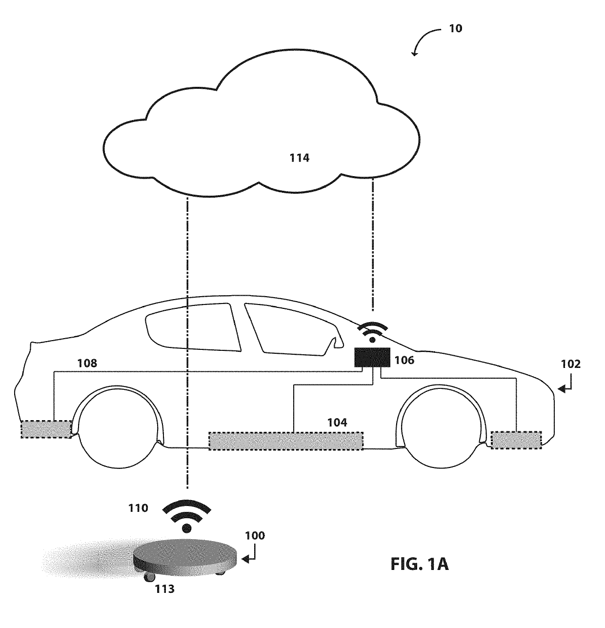
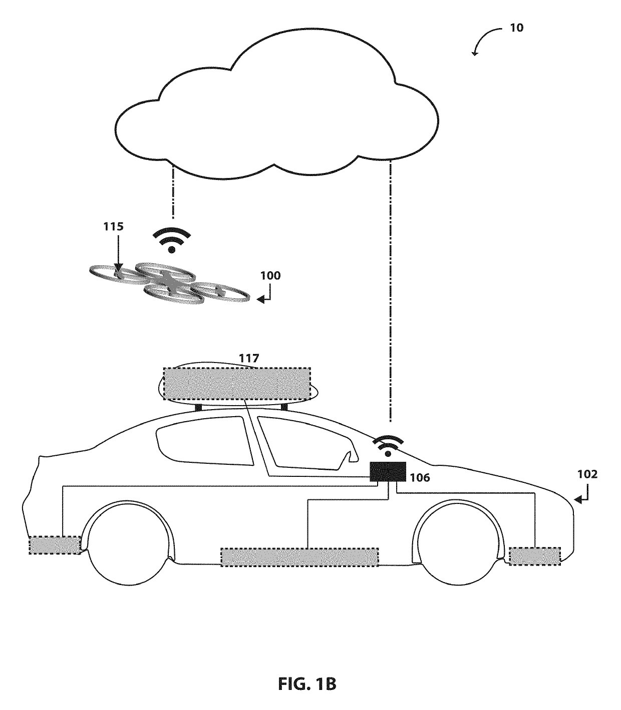
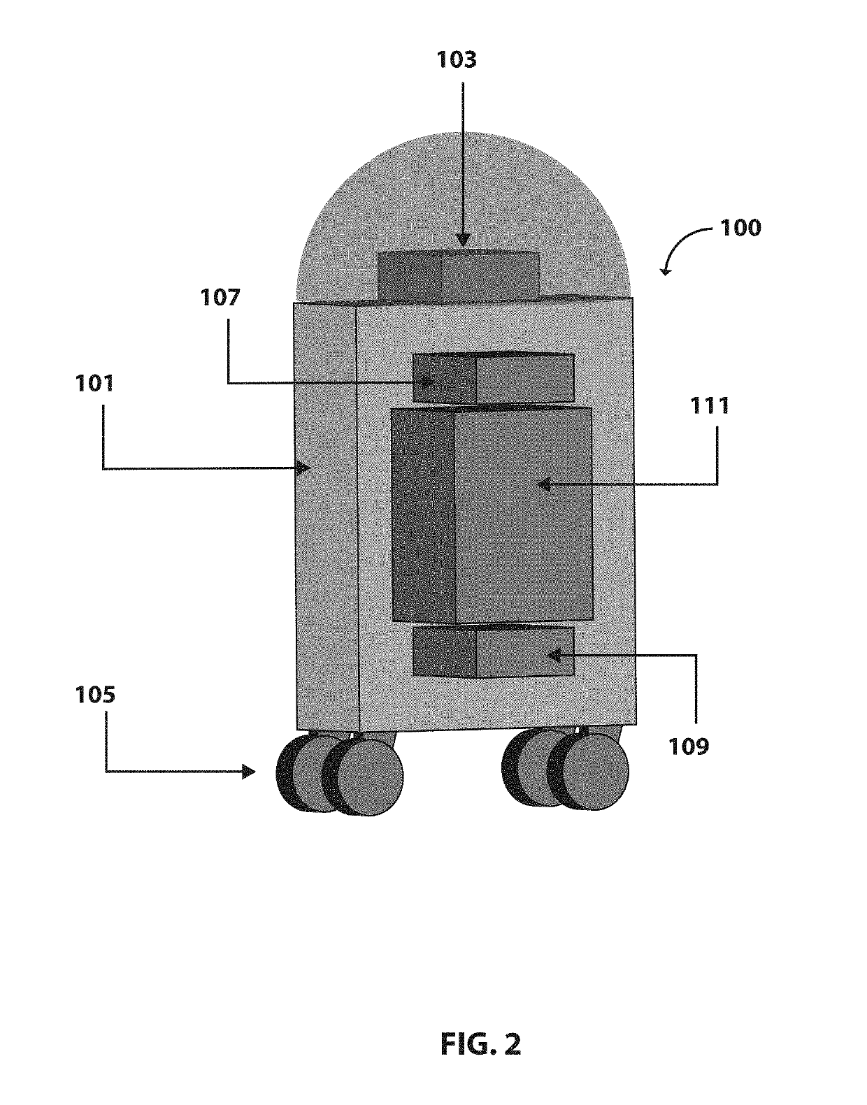
A power delivery system having a power receiver and a mobile power transmitter. The mobile power transmitter having a control system having a sensor configured to monitor status data and a processing unit; a drive system operably coupled to the control system to provide propulsion of the mobile power transmitter; a communication system configured to communicate with the power receiver or a user preparing to charge the power receiver identification information; a power source system coupled to the control system configured to provide power for transfer to the power receiver; and a charging system coupled to the control system configured to transmit power from the power storage system to the power receiver. The control system processes the communicated identification information and the monitored status data and instructs the drive system of the mobile power transmitter to relocate to a location of the power receiver.

Description

CROSS-REFERENCE TO RELATED APPLICATIONS[0001]This application claims the benefit of U.S. Provisional Application No. 62 / 654,707 filed on Apr. 9, 2018. The entire disclosure of the above-referenced application is incorporated herein by reference.FIELD[0002]The present disclosure relates to charging and, more particularly, relates to a system and method for charging a power receiver with a mobile power transmitter.BACKGROUND AND SUMMARY[0003]This section provides background information related to the present disclosure that is not necessarily prior art. This section provides a general summary of the disclosure, and is not a comprehensive disclosure of its full scope or all of its features.[0004]With the recent popularity of electric consumers (EC), increasing effort is focused on addressing several challenges associated with battery-operated devices: 1) the low charge capacity of batteries requires frequent charging, 2) the low re-charging rate of conventional batteries, and 3) the as...

Claims


Application Information

Patent Timeline
Patent Type & Authority Applications(United States)
IPC IPC(8): B60L53/12H02J7/02H02J50/10H02J50/90H02J50/80B60L53/14B60L53/30B60L53/65B67D7/04
CPCB60L53/65B67D7/0401B60L53/305H04W4/44H02J50/10H02J50/90B60L53/14H02J7/025B67D2007/043H02J50/80B60L53/12H04W4/023B60L53/37B60L53/38B60L53/57B60L53/66B60L53/665B60L53/68B60L53/10B60L53/32Y02T90/16Y02T90/167Y02T10/70Y02T90/14Y02T10/7072Y02T90/12Y04S30/14
Inventor AKHAVAN-TAFTI, MOJTABA
Owner RGT UNIV OF MICHIGAN
Learn More