Brake system with two pressure sources, and two methods for operating a brake system

a brake system and pressure source technology, applied in the field of brake systems, can solve problems such as pressure dissipation in the brake wheel, and achieve the effect of reducing the outlay for electrical connections

Active Publication Date: 2019-10-10
CONTINENTAL TEVES AG & CO OHG
View PDF3 Cites 15 Cited by
  • Summary
  • Abstract
  • Description
  • Claims
  • Application Information

AI Technical Summary

Benefits of technology

[0013]An aspect of the invention is based on the consideration that, in the case of a brake assembly with two electrically actuatable pressure provision devices, it would be advantageous to provide the driver with a fall-back level with active pressure build-up in the wheel brakes even in the event of a failure of the electrical supply of a pressure provision device. In this way, the brake assembly does not need to be designed for mechanical intervention by the driver in the fall-back level, and it is for example possible for a dry simulator or master brake cylinder to be used.
[0014]As has now been identified, this can be achieved by virtue of two separate on-board electrical systems being provided, wherein each of the two on-board electrical systems feeds one of the two pressure provision devices. In this way, it is always possible for pressure to be actively built up even in the event of a failure of one on-board electrical system, such that, as it were, a fall-back level is made possible in the by-wire operating mode.
[0015]It is preferable for each of the electrically actuatable pressure provision devices to be fed in each case by exactly one or by only one of the two on-board electrical systems. This reduces the outlay for the electrical connections.

Problems solved by technology

In the reverse situation, the movement of the linear actuator back in the direction of its rest position leads to a pressure dissipation in the wheel brakes.

Method used


Image

  • Brake system with two pressure sources, and two methods for operating a brake system
  • Brake system with two pressure sources, and two methods for operating a brake system
  • Brake system with two pressure sources, and two methods for operating a brake system

Examples


Embodiment Construction

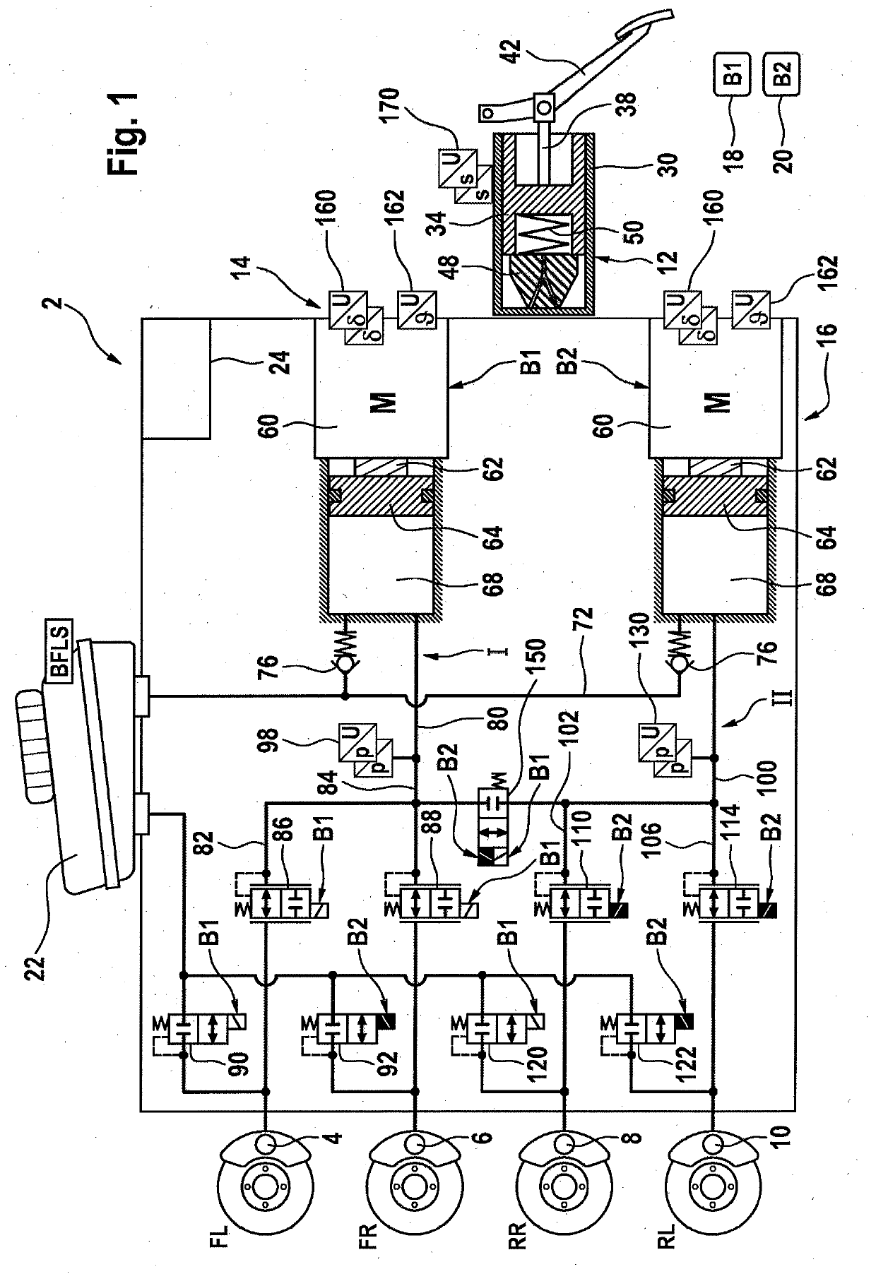
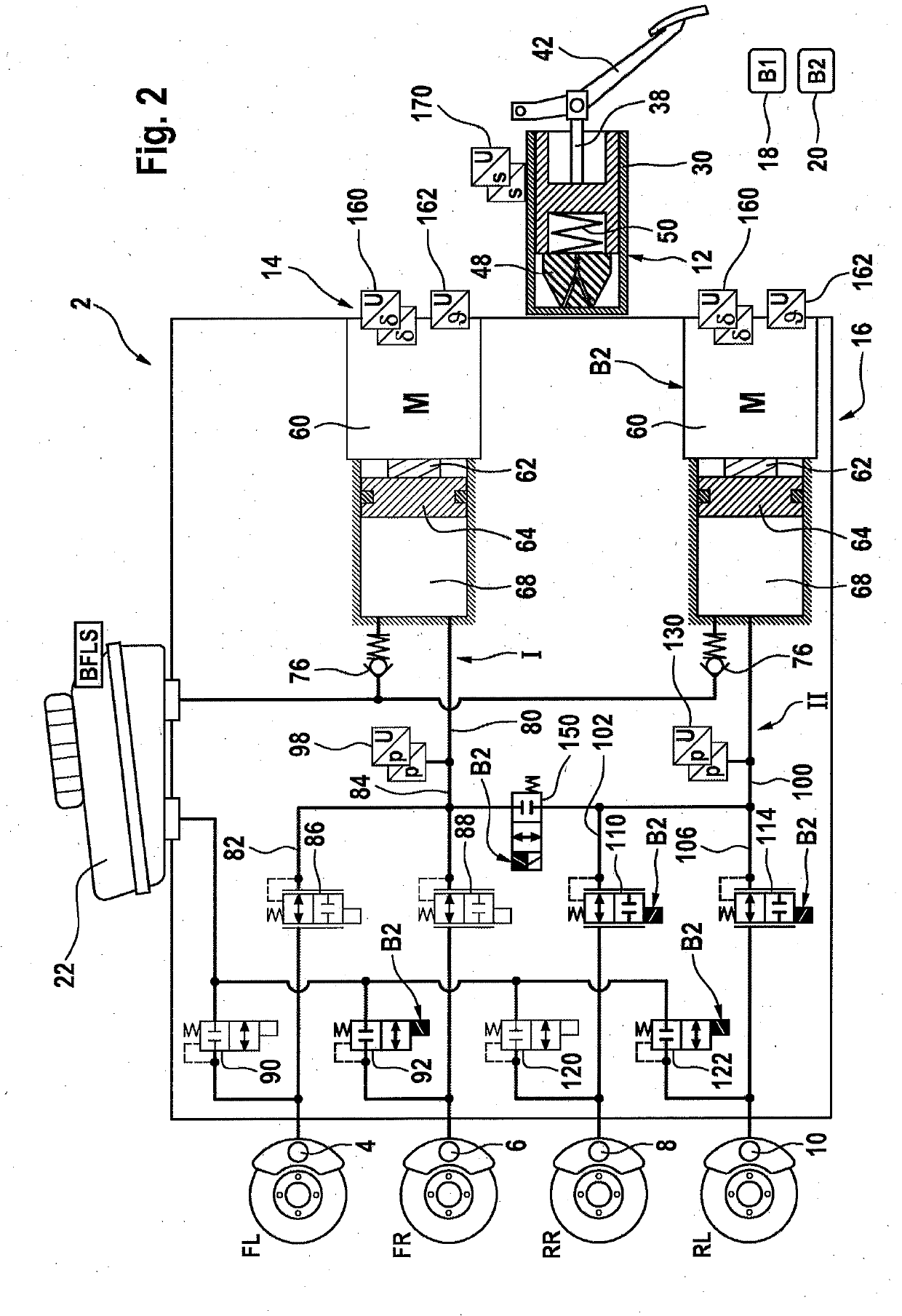
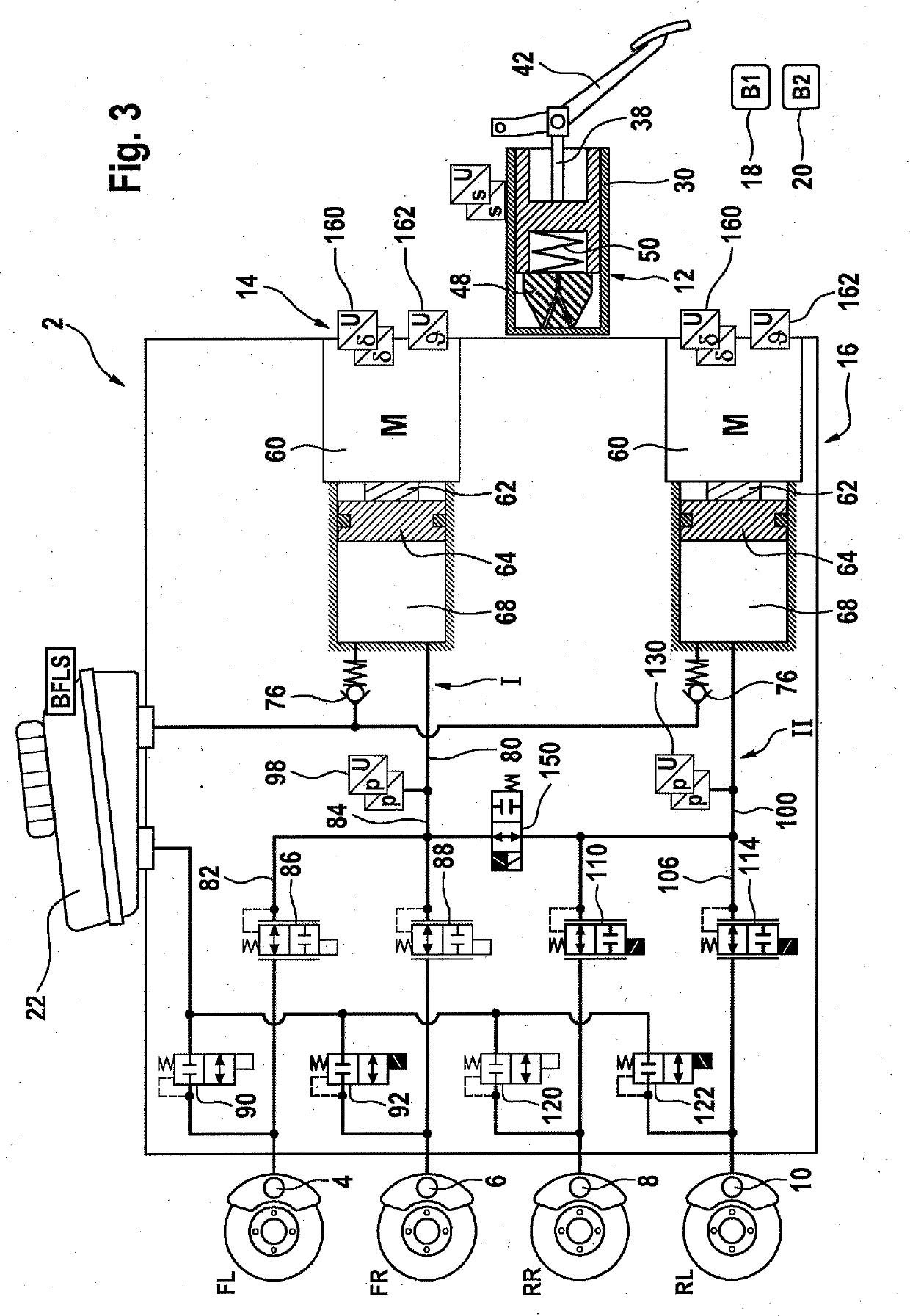
[0037]A brake system 2 illustrated in FIG. 1 comprises four hydraulically actuatable wheel brakes 4, 6, 8, 10, a simulator 12, two pressure provision devices 14, 16, two independent on-board electrical systems 18, 20, a pressure medium reservoir 22 which is at atmospheric pressure, and an open-loop and closed-loop control unit 24.

[0038]The simulator 12 which is formed in the manner of a master brake cylinder comprises a master brake cylinder piston 34 which is arranged in a master brake cylinder housing 30 and which is coupled by means of a piston rod 38 to a brake pedal 42. In the event of actuation of the brake pedal 42, the master brake cylinder piston 34 is pressed against an elastic element 48 which is likewise arranged in the master brake cylinder housing 30. A further elastic element 50 supports the piston 34 on the elastic element 48 and, when the brake pedal is not actuated, pushes the piston 34 into its rest position. The simulator 12 is of dry design, that is to say it co...


PUM


Abstract

A brake system, including four hydraulically actuatable wheel brakes. Each wheel brake is assigned in each case one outlet valve which is closed when electrically deenergized. Each wheel brake is assigned in each case one inlet valve which is open when electrically deenergized. The brake system furthermore includes a simulator which is actuatable by a brake pedal, wherein two pressure provision devices are provided for actively building up pressure in the wheel brakes, two brake circuits are hydraulically formed, wherein, in each brake circuit, in each case one pressure provision device is hydraulically connected to two wheel brakes, and wherein two separate on-board electrical systems are provided, and wherein each pressure provision device is fed in each case by one of the two on-board electrical systems.

Description

CROSS REFERENCE TO RELATED APPLICATIONS[0001]This application is the U.S. National Phase Application of PCT International Application No. PCT / EP2017 / 080297, filed Nov. 24, 2017, which claims priority to German Patent Application No. 10 2016 225 537.1, filed Dec. 20, 2016, the contents of such applications being incorporated by reference herein.FIELD OF THE INVENTION[0002]The invention relates to a brake system, comprising four hydraulically actuatable wheel brakes, wherein each wheel brake is assigned in each case one outlet valve which is closed when electrically deenergized, wherein each wheel brake is assigned in each case one inlet valve which is open when electrically deenergized, comprising a simulator which is actuatable by means of a brake pedal, wherein two pressure provision devices are provided for actively building up pressure in the wheel brakes. The invention furthermore relates to a corresponding operating method.BACKGROUND OF THE INVENTION[0003]In motor vehicle engin...

Claims


Application Information

Patent Timeline
Patent Type & Authority Applications(United States)
IPC IPC(8): B60T13/68B60T8/40B60T7/04B60T8/32B60T13/16
CPCB60T2270/82B60T13/168B60T13/161B60T2270/403B60T8/326B60T2270/402B60T13/686B60T8/4086B60T2270/10B60T7/042B60T2270/413B60T8/3645B60T8/4081B60Y2400/81
Inventor MAJ, BARTOSZKOLLMANN, HOLGERMILIC, TOMISLAVSCHÖNBOHM, ALEXANDERSCHRÖDER, RALFLENZ, MARCBLETZ, MARCUSSCHMIDT, JURIJDINKEL, DIETER
Owner CONTINENTAL TEVES AG & CO OHG
Why Eureka
Try Eureka