Moving vehicles in a smart environment

a technology of moving vehicles and smart environments, applied in simultaneous traffic control systems, broadcast service distribution, instruments, etc., can solve the problems of rare to find an automobile without various safety and protection systems, and associated angular resolution of microwave radar, etc., to achieve the effect of increasing the thickness of the padding and increasing the number of padding

Active Publication Date: 2019-10-10
ANVARI KIOMARS
View PDF5 Cites 14 Cited by
  • Summary
  • Abstract
  • Description
  • Claims
  • Application Information

AI Technical Summary

Benefits of technology

[0031]In one aspect, each wireless sensor's transmit signal with embedded IP address is fragmented. Then the wireless sensor each time transmits a fragment of the transmit signal and receives the reflected fragment of transmit signal until all fragments are transmitted. This is done to improve accuracy as well as reduce complexity.
[0041]In one aspect, the wireless transceiver (wireless sensor) changes its carrier frequency and modulation for better, faster transmission and reception of information.
[0045]In one aspect, both wireless sensor and image sensor independently calculate the same parameters of surrounding environment for better detection of potential impact with an object.
[0053]In another aspect, immediately after impact depending on the force of impact or configured data a number of nested airbags starting from the last and smallest one will collapse by releasing their air using a deflating mechanism. This way the outer airbag and nested airbags that are not deflated partially collapse and provide wider protection.
[0056]In one aspect, the protection system uses expandable pad to protect the moving or flying vehicle / object by applying voltage to two ends of the pad. This results in the pad thickness to increase and provide more padding for the moving or flying vehicle / object.

Problems solved by technology

Developing intelligent transportation systems which take into consideration the economical, environmental, and safety factors of the modern society, is one of the main challenges of this century.
For instant, just a few years ago, automobiles seldom had very sophisticated safety systems.
Now, it is rare to find an automobile without various safety and protection systems.
There are multiple problems of these automobile collision avoidance systems when microwave radars are used.
One major issue is related to the beam width that is the angular width of the main lobe of the radar, and the associated angular resolution of the microwave radar.
With the limitation of the antenna size, it is very difficult to make reasonable size microwave radar with beam width less than 3 degrees.
At the desired scanning distance, this beam width will scan an area which is much too big and thus is too nonspecific and difficult to differentiate the received echoes.
On highways with divided lanes the microwave radar will receive echoes from cars 2 or 3 lanes away and has difficulty in differentiating them from echoes coming from objects in the same lane.
Because of the poor angular resolution of microwave radars, the direction of objects cannot be specifically determined and objects too close to one another cannot be separated.
The angular resolution of microwave radars is not small enough for them to be effectively used to monitor roadway traffic.
The other issue is that the microwave radars have difficulty in distinguishing radar signals coming from adjacent cars with similar equipment.
If there are more than two cars with the same radar equipment on the same scene, the signals become very confusing.
The ultrasonic ranging and detecting device's angular resolution is also too poor to be effectively used in roadway traffic monitoring.
The ultrasonic devices have even more problems than the microwave radars in determining the direction and location of echoes precisely, in the detection of directional change of objects and in avoiding signals coming from adjacent vehicles with similar equipment
Obviously such complex systems are expensive to build and will have a lower inherent reliability.
Although the above systems may find utility in avoiding front and rear collisions they are not adapted for early warning of imminent side collisions.
However, compressed air is more expensive than the other three utilities when evaluated on a per unit energy delivered basis.

Method used


Image

  • Moving vehicles in a smart environment
  • Moving vehicles in a smart environment
  • Moving vehicles in a smart environment

Examples


Embodiment Construction

[0074]Reference will now be made in detail to embodiments of the present technology, examples of which are illustrated in the accompanying drawings. While the technology will be described in conjunction with various embodiment(s), it will be understood that they are not intended to limit the present technology to these embodiments. On the contrary, the present technology is intended to cover alternatives, modifications and equivalents, which may be included within the spirit and scope of the various embodiments as defined by the appended claims.

[0075]Furthermore, in the following description of embodiments, numerous specific details are set forth in order to provide a thorough understanding of the present technology. However, the present technology may be practiced without these specific details. In other instances, well known methods, procedures, components, and circuits have not been described in detail as not to unnecessarily obscure aspects of the present embodiments.

[0076]FIG. ...


PUM


Abstract

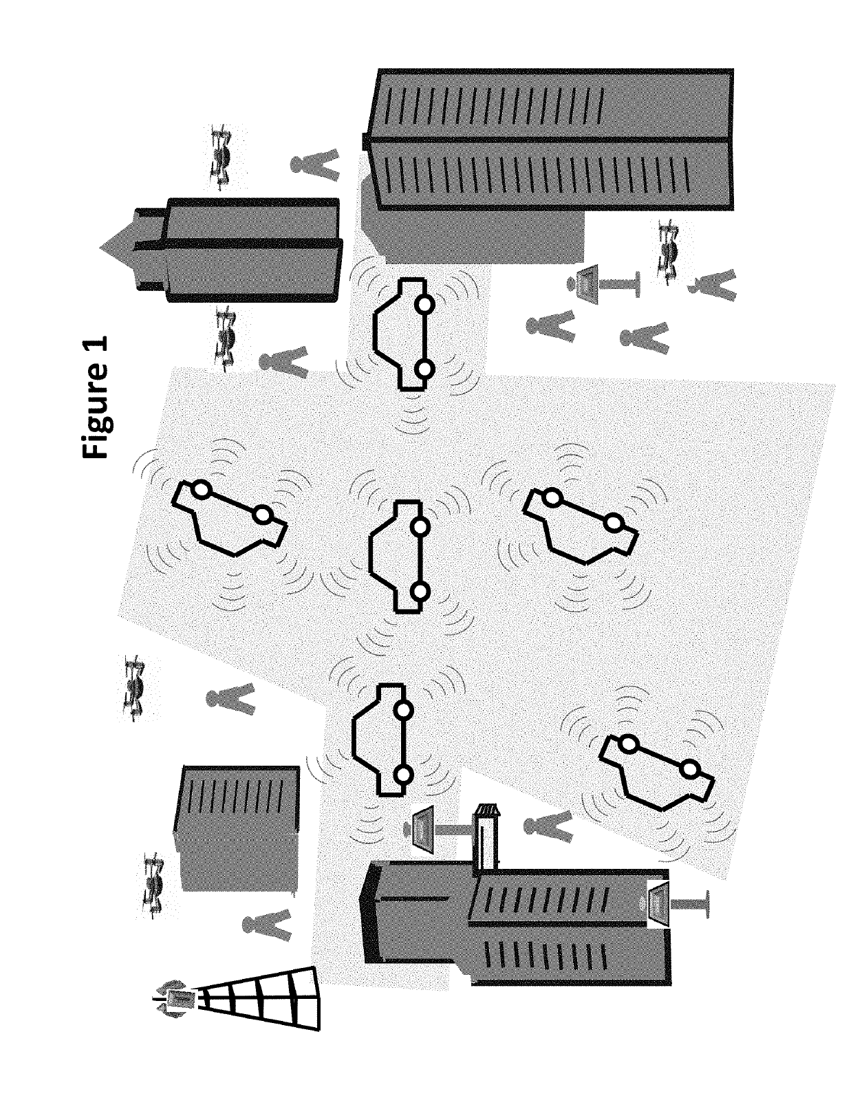
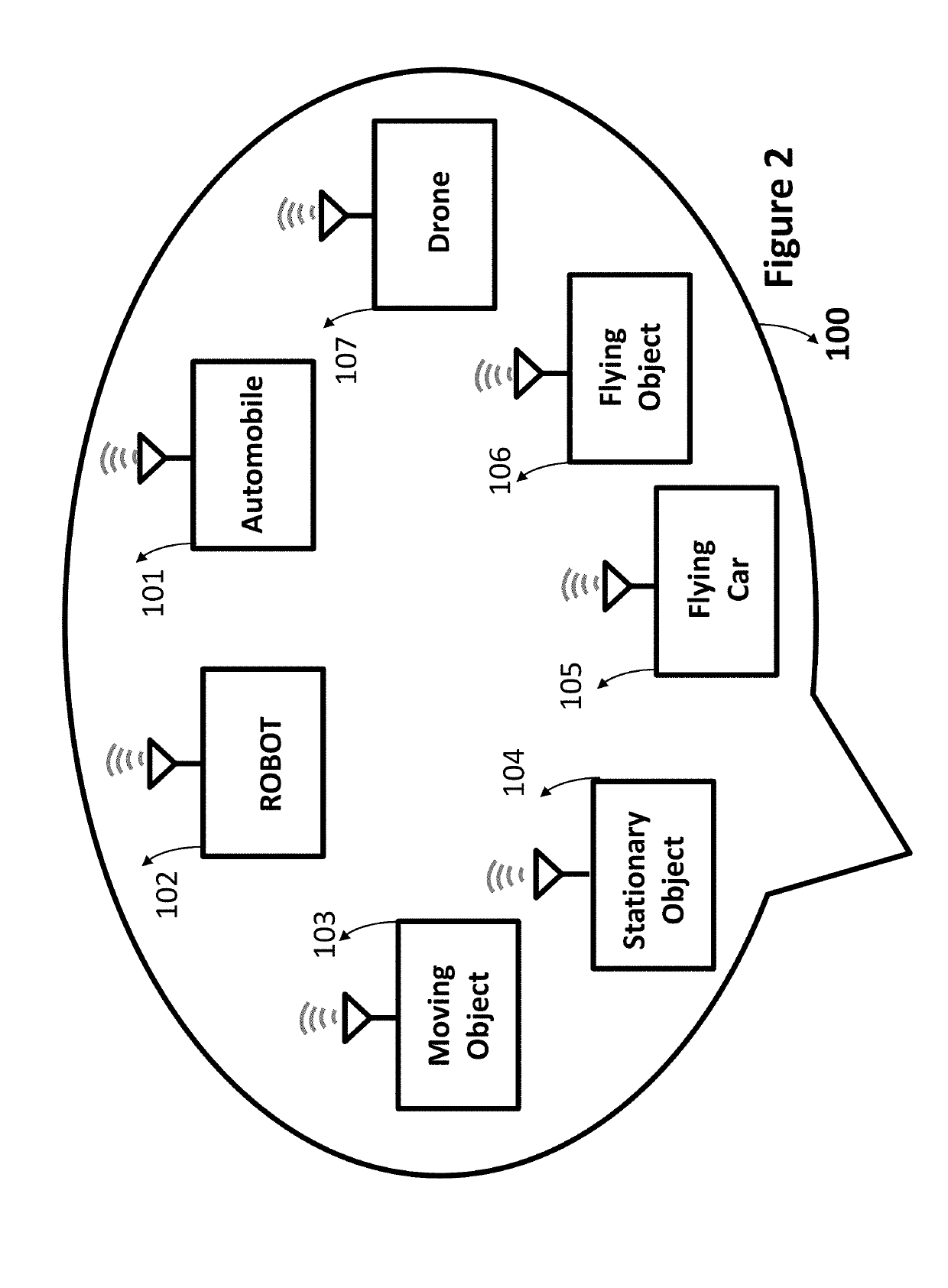
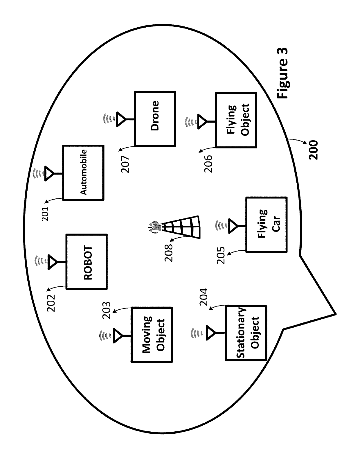
Smart environments represent the next evolutionary development step in transportation systems. Like any functioning organism, the smart environment relies first and foremost on sensory data from the real world. Sensory data comes from multiple sensors of different modalities in distributed locations. Sensors used by various moving, flying and stationary objects exchange information through broadcasting or indirectly through public or private networks. The information helps various moving vehicles and stationary objects coexist and operate freely without any interruption, interference, and collision.

Description

[0001]The application claims priority to the following related applications and included here is as a reference.[0002]Application: U.S. patent application Ser. No. 15 / 071,910 filed Mar. 16, 2016 and entitled “A CONTROL ALGORITHM FOR WIRELESS SENSOR TO ESTIMATE AND CALCULATE ENVIRONMENTAL PARAMETERS”.[0003]Application: U.S. patent application Ser. No. 15 / 193,373 filed Jun. 27, 2016 and entitled “PROTECTION AND GUIDANCE GEAR OR EQUIPMENT WITH IDENTITY CODE AND IP ADDRESS”.[0004]Application: U.S. patent application Ser. No. 15 / 888,175 filed Feb. 5, 2018 and entitled “PROTECTION FOR MOVING EQUIPMENTS AND OBJECTS”.BACKGROUND[0005]Developing intelligent transportation systems which take into consideration the economical, environmental, and safety factors of the modern society, is one of the main challenges of this century. Progress in the fields of mobile robots, control architectures, advanced technologies, and computer vision allows us to now envisage the integration of autonomous and d...

Claims


Application Information

Patent Timeline
Patent Type & Authority Applications(United States)
IPC IPC(8): G08G1/16G08G1/01G08G5/04G08G5/00G01S19/13G01S13/93G01S13/87G01S13/931G01S13/933
CPCG08G1/166H04L67/12G01S13/878G08G1/165G08G5/0043G01S13/9303H04W84/18G08G1/164G08G5/0013G01S19/13G08G1/0112G08G1/012G08G5/04G01S13/931G08G1/0125H04W4/40H04W4/02H04W4/06H04W4/38G01S13/933G08G1/163G08G7/02G08G5/045G08G5/0008
Inventor ANVARI, KIOMARS
Owner ANVARI KIOMARS
Why Eureka
Try Eureka