Control apparatus for vehicle drive-force transmitting apparatus

a control apparatus and transmission device technology, applied in the direction of gearing control, gearing elements, gearing, etc., can solve the problems of transfer element slippage, and achieve the effect of preventing or reducing the slippage of the transfer elemen

Active Publication Date: 2019-10-17
TOYOTA JIDOSHA KK
View PDF4 Cites 3 Cited by
  • Summary
  • Abstract
  • Description
  • Claims
  • Application Information

AI Technical Summary

Benefits of technology

[0022]In the control apparatus according to the eighth aspect of the invention, when the target gear ratio of the continuously-variable transmission mechanism is set to the transient target gear ratio, the rate of change of the transient target gear ratio is made lower in the transient state of switching of the operation state of the second engagement device between the fully engaged state and the fully released state than in the f...

Problems solved by technology

However, if the pulley hydraulic pressure applied to the primary pulley is temporarily reduced by a large degree so as to immediately change the actual gear ratio to the highest gear ratio, there is a risk that s...

Method used


Image

  • Control apparatus for vehicle drive-force transmitting apparatus
  • Control apparatus for vehicle drive-force transmitting apparatus
  • Control apparatus for vehicle drive-force transmitting apparatus

Examples


embodiment

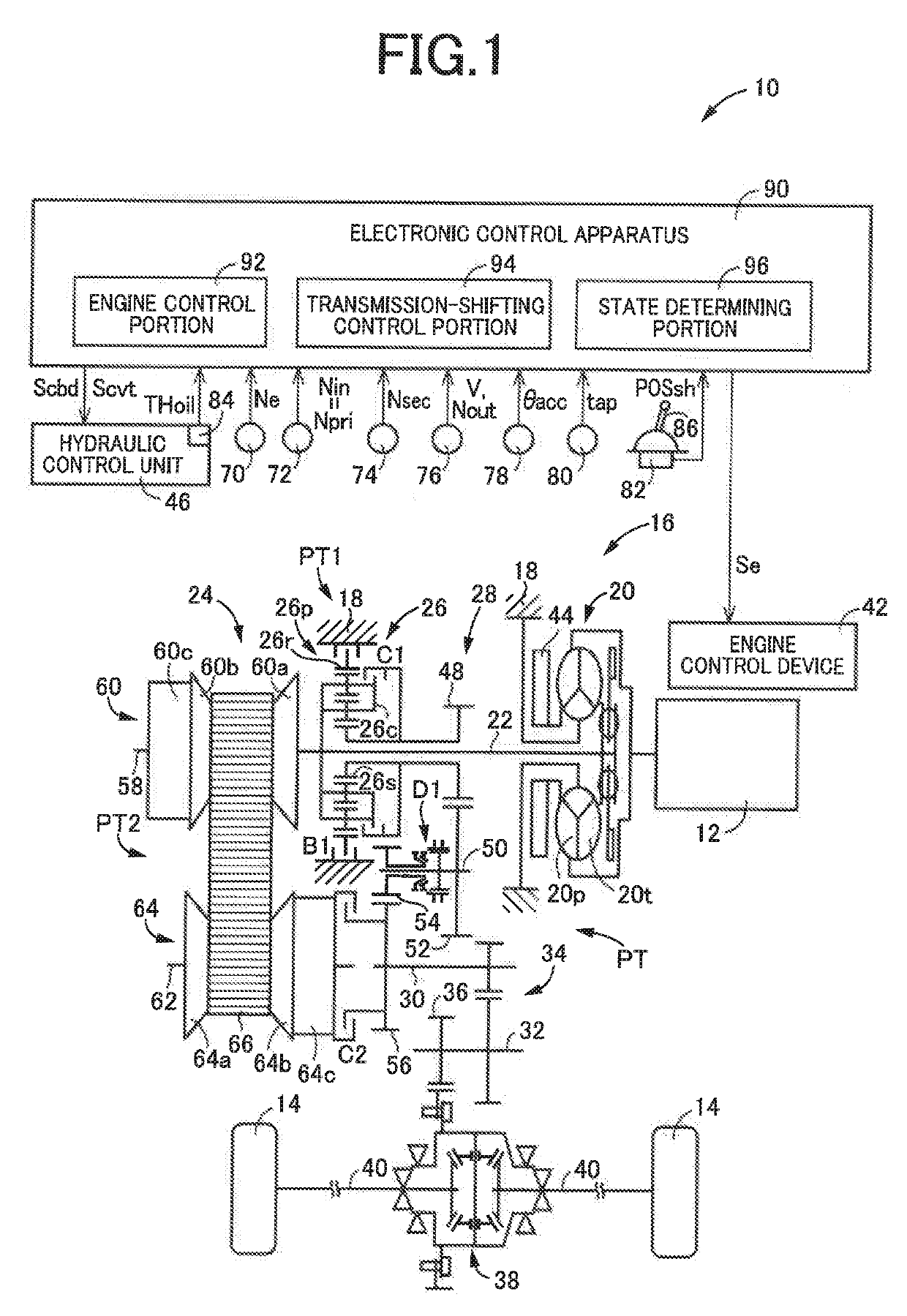
[0041]FIG. 1 is a schematic view showing a construction of a vehicle 10 to be controlled by a control apparatus according to the present invention, and major control functions and control portions of the control apparatus. As shown in FIG. 1, the vehicle 10 is provided with an engine 12 functioning as a drive force source configured to generate a drive force, drive wheels 14 and a drive-force transmitting apparatus 16 that is provided in drive-force transmitting paths between the engine 12 and the drive wheels 14.

[0042]The drive-force transmitting apparatus 16 includes a non-rotary member in the form of a casing 18, a fluid-operated type drive-force transmitting device in the form of a known torque converter 20 that is connected to the engine 12, an input shaft 22 connected to the torque converter 20, a continuously-variable transmission mechanism 24 connected to the input shaft 22, a forward / reverse switching device 26 connected to the input shaft 22, a gear mechanism 28 which is p...


PUM


Abstract

A control apparatus for a vehicle drive-force transmitting apparatus including a gear mechanism and a continuously-variable transmission mechanism and defining first and second drive-force transmitting paths. When the continuously-variable transmission mechanism is in a failure state in which an actual gear ratio of the continuously-variable transmission mechanism is not the highest gear ratio as a target gear ratio, the control apparatus sets the target gear ratio to a transient target gear ratio that is gradually changed toward the highest gear ratio, for causing the actual gear ratio to be gradually changed toward the highest gear ratio. A rate of change of the transient target gear ratio is higher in a state in which a drive force is transmitted through the first drive-force transmitting path by the gear mechanism, than in a state in which the drive force is transmitted through the second drive-force transmitting path by the continuously-variable transmission mechanism.

Description

[0001]This application claims priority from Japanese Patent Application No. 2018-078763 filed on Apr. 16, 2018, the disclosure of which is herein incorporated by reference in its entirety.FIELD OF THE INVENTION[0002]The present invention relates to a control apparatus for a drive-force transmitting apparatus that is to be provided in a vehicle, wherein the drive-force transmitting apparatus has a plurality of drive-force transmitting paths that are provided in parallel with each other between a drive force source and drive wheels of the vehicle.BACKGROUND OF THE INVENTION[0003]There is known a control apparatus for a drive-force transmitting apparatus that is to be provided in a vehicle having a drive force source and drive wheels, wherein the drive-force transmitting apparatus includes: an input rotary member to which a drive force is to be transmitted from the drive force source; an output rotary member from which the drive force is to be outputted to the drive wheels; a gear mech...

Claims


Application Information

Patent Timeline
IPC IPC(8): F16H61/12F16H37/08F16H61/662F16H9/18
CPCF16H2037/0866F16H37/0846F16H9/18F16H61/12F16H2061/1232F16H61/662F16H37/022F16H61/66236F16H2037/026F16H2061/1256
Inventor HATTORI, KUNIOWASHIO, TAICHISHIMAZU, TAKURO
Owner TOYOTA JIDOSHA KK
Why Eureka
Try Eureka