
Nonreducing dielectric ceramic and ceramic electronic component using same

a technology of dielectric ceramics and electronic components, applied in the direction of fixed capacitor details, inorganic insulators, fixed capacitors, etc., can solve the problems of inability to use copper, silver has a low melting point, and the cost of the resultant ceramic electronic component is increased

Inactive Publication Date: 2002-09-19
MURATA MFG CO LTD
View PDF0 Cites 15 Cited by
  • Summary
  • Abstract
  • Description
  • Claims
  • Application Information

AI Technical Summary

Benefits of technology

[0018] The nonreducing dielectric ceramic of the present invention can be cofired with copper or a copper alloy, and even if firing is performed in a neutral or reducing atmosphere, the insulation resistance and the dielectric loss are not greatly degraded, and it is possible to provide a low rate of change in capacitance with temperature within .+-.60 ppm / .degree. C.
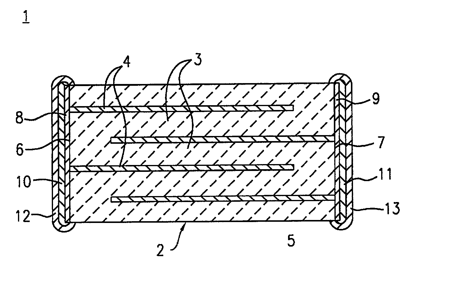
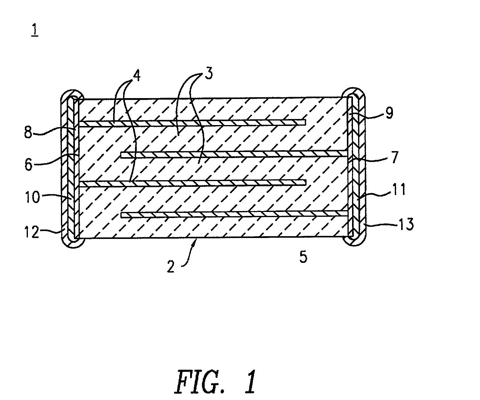
[0019] Consequently, when such a nonreducing dielectric ceramic is used for an electronic component body in a ceramic electronic component including a conductor in contact with the electronic component body, it is possible to produce a ceramic electronic component which is highly reliable with respect to electrical characteristics, such as insulation resistance and dielectric loss, and which has superior temperature stability.
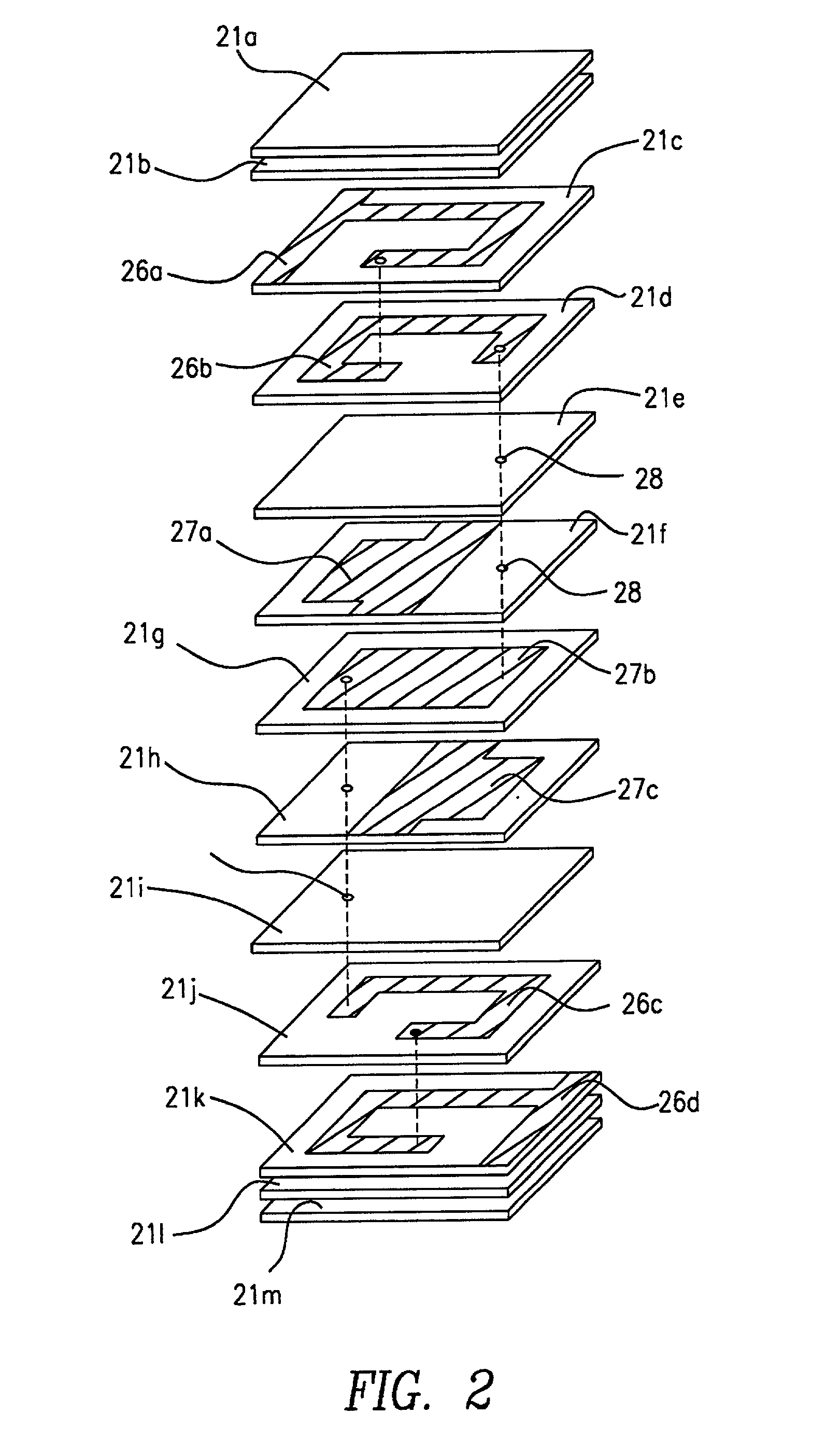
[0022] If the nonreducing dielectric ceramic is used as the ceramic constituting the dielectric ceramic layers, reliability in the electric characteristics, such as insulation resistance and dielectric loss, can be enhanced, and the rate of change in capacitance with temperature can be decreased. Consequently, the nonreducing dielectric ceramic of the present invention can be advantageously used as dielectric materials for temperature compensating type ceramic capacitors, microwave dielectric resonators, multilayered circuit components, etc.
[0023] In such a ceramic electronic component of the present invention, preferably, the conductor or the internal electrode includes elemental copper or a copper alloy as a conductive material. Since copper or a copper alloy can be used as the conductive material contained in the conductor or the internal electrode in the ceramic electronic component, the cost of the ceramic electronic component can be kept low, and also superior high frequency characteristics can be attained.

Problems solved by technology

Because gold or silver used as the conductive material are relatively expensive, the cost of the resultant ceramic electronic component is increased.
Also, silver has a low melting point of approximately 960.degree. C., and sintering of ceramics below this temperature often causes difficulties.
Furthermore, conductors, such as internal electrodes, are formed in contact with a ceramic in monolithic ceramic electronic components, and the use of silver for the conductors may result in migration.
It is therefore not possible to use copper as the material for a conductor which is cofired with these crystal phases.
Additionally, if the tungsten-bronze-type crystal phase is fired in a neutral or reducing atmosphere, it becomes semiconductive because it has a poor nonreducing property, resulting in degradation in insulation resistance and dielectric loss.
Furthermore, since the tungsten-bronze-type crystal phase has a high rate of change in capacitance with temperature of approximately -100 ppm / .degree. C., the applications of the ceramic electronic component containing this crystal phase is limited.

Method used


Image

  • Nonreducing dielectric ceramic and ceramic electronic component using same
  • Nonreducing dielectric ceramic and ceramic electronic component using same
  • Nonreducing dielectric ceramic and ceramic electronic component using same

Examples


example 2

[0079] In Example 2, samples were produced in order to check the influence of the contents of Mn, the glass component, Cu, and V as the secondary constituents.

[0080] Ceramic sintered compacts were produced in the same manner as that in Example 1, apart from the fact that the individual starting materials were prepared so as to satisfy the compositions shown in Table 3.

3 TABLE 3 Principal Constituent Secondary Constituent Composition Firing aBaCO.sub.3--bTiO.sub.2--cRE.sub.2-Ti.sub.2O.sub.7 MnCO.sub.3 CuO VO.sub.5 / 2 Glass Sample Temperature a b c per 100 per 100 per 100 component No. .degree. C. mole % mole % RE mole % 100 moles Ti 100 moles Ti 100 moles Ti parts by weight 19 1,000 14.28 42.86 Nd 42.86 7.0 moles 2.0 moles 0.5 mole 10.0 22 1,020 14.28 42.86 Nd 42.86 3.0 moles 2.0 moles 0.5 mole 10.0 23 990 14.28 42.86 Nd 42.86 25.0 moles 2.0 moles 0.5 mole 10.0 24 980 14.28 42.86 Nd 42.86 35.0 moles 2.0 moles 0.5 mole 10.0 25 1,020 14.28 42.86 Nd 42.86 7.0 moles 2.0 moles 0.5 mole 3.0...


PUM

PropertyMeasurementUnit
melting pointaaaaaaaaaa
sizeaaaaaaaaaa

Abstract

A nonreducing dielectric ceramic contains a tungsten-bronze-type crystal phase including at least Ba, RE and Ti as elements, and a pyrochlore-type crystal phase including at least RE and Ti as elements, where RE is at least one rare-earth element. The relationship 0.10<=b / (a+b)<=0.90 is satisfied, where a is the maximum peak intensity assigned to the tungsten-bronze-type crystal phase and b is the maximum peak intensity assigned to the pyrochlore-type crystal phase determined by X-ray diffractometry. A ceramic electronic component includes an electronic component body composed of the nonreducing dielectric ceramic and a conductor in contact with the nonreducing dielectric ceramic.

Description

[0001] 1. Field of the Invention[0002] The present invention relates to nonreducing dielectric ceramics and ceramic electronic components, such as monolithic ceramic capacitors and monolithic LC filters, using the nonreducing dielectric ceramics. More particularly, the invention relates to improvements in nonreducing dielectric ceramics so that cofiring with copper or copper alloys can be performed.[0003] 2. Description of the Related Art[0004] Dielectric ceramics containing tungsten-bronze-type crystal phases, such as a BaRE.sub.2Ti.sub.4O.sub.12-type crystal phase and a BaRE.sub.2Ti.sub.5O.sub.14-type crystal phase, where RE is a rare-earth metallic element, which are used for ceramic electronic components such as temperature compensating type ceramic capacitors, are disclosed in Japanese Examined Patent Application Publication No. 55-20602, etc. Since the dielectric loss is small (the Q factor is high), they are suitable for use in the ceramic electronic components, and since the...

Claims


Application Information

Patent Timeline
Patent Type & Authority Applications(United States)
IPC IPC(8): C04B35/462C04B35/468H01B3/12H01G4/12H01G4/40C04B35/46
CPCC04B35/462C04B35/468C04B35/4682H01G4/1227H01G4/129H01G4/40H01G4/12
Inventor NAITO, MASAHIRO
Owner MURATA MFG CO LTD
Learn More