Method of sted microscopy

a microscopy and optical filter technology, applied in the field of optical microscopy, can solve the problems of significant loss of luminescence signal by at least 30%, and use of regular high-performance optical filters like notch filters will not help, so as to achieve the effect of increasing resolution

Active Publication Date: 2019-10-24
UNIVSKLINIKUM JENA
View PDF0 Cites 1 Cited by
  • Summary
  • Abstract
  • Description
  • Claims
  • Application Information

AI Technical Summary

Benefits of technology

[0019]An object of the invention therefore is to modify a method for optical microscopy based on STED to allow an even

Problems solved by technology

However, using the wavelength in the range of the FWHM alone is not enough: As the second wavelength is within the emission spectrum of the respective dye particles, it must be taken care that the signal is not distorted by backscattered STED laser light of the second wavelength.
Using regular high-performa

Method used


Image

  • Method of sted microscopy
  • Method of sted microscopy
  • Method of sted microscopy

Examples


Embodiment Construction

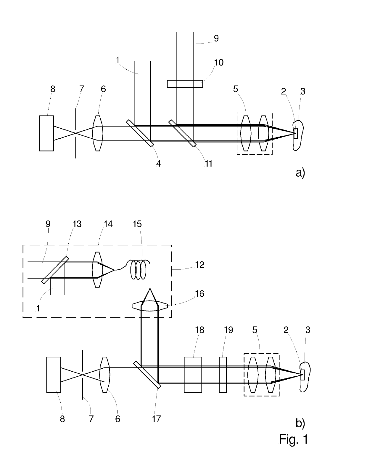
[0040]FIG. 1a) shows a typical setup for STED microscopy which is very similar to that of a confocal scanning microscope. In STED microscopy a first laser beam 1 with light having a first wavelength is used to excite dye particles contained in a region 2 of a sample 3. The region can be either two- or three-dimensional, depending on the type of scanning. The sample 3 or at least the region 2 of the sample 3 is marked with the dye particles which emit luminescence, in particular fluorescence when excited. The first wavelength usually corresponds to the absorption wavelength of the dye particles used. The first laser beam 1 is coupled into the beam path by a dichroic mirror 4. Through an objective lens 5 it is directed onto the sample. Prior to entering the objective lens 5, the beam passes a scan unit which is not shown here. The scan unit has the purpose of moving the focal spot which the first laser beam 1 forms in the region 2 of the sample 3 in lateral directions and / or in axial ...


PUM


Abstract

A method for optical microscopy, including using a first laser beam to excite dye particles in a sample region with light having a first wavelength. A second laser beam with a second wavelength based on the emission spectrum of the excited particles is used to de-excite the excited particles. The first and second beams have first and second respective intensity distributions which are spatially different when co-aligned; the second profile has a minimum where the first has a maximum. The region is once concurrently illuminated with the first and second beams, and an emission signal is detected. For each scanning point, the region is illuminated also with a pulse of the second laser beam or continuously prior to or after illuminating the region of the sample concurrently with both lasers. The illumination with only the second laser beam defines a background signal that is subtracted from the emission signal.

Description

PRIORITY CLAIM[0001]The present application is a National Phase entry of PCT Application No. PCT / EP2017 / 081887, filed Dec. 7, 2017, which claims priority from European Patent Application 16204063.8, filed Dec. 14, 2016, the disclosures of which are hereby incorporated by reference herein in their entirety.FIELD OF THE INVENTION[0002]The invention relates to a method for optical microscopy by scanning a sample. The method is related to so-called optical super-resolution microscopy based on stimulated emission depletion (STED).BACKGROUND OF THE INVENTION[0003]STED microscopy is one of the methods which can resolve spatially details of a microscopic sample below the fundamental Abbe diffraction limit which corresponds to about half of the wavelength of the light to be detected. For example, a single molecule having a length of about 1 nm and emitting fluorescent light at a wavelength of 600 nm will show in an image taken with a common microscope as a round spot with a diameter of about...

Claims


Application Information

Patent Timeline
IPC IPC(8): G02B21/00G02B27/58G02B5/20
CPCG02B21/008G02B21/0064G02B21/0076G02B27/58G02B21/0072G02B5/202G02B5/28
Inventor BOERSCH, MICHAEL
Owner UNIVSKLINIKUM JENA
Why Eureka
Try Eureka