

Molding apparatus that molds composition on substrate by using mold, molding method, and manufacturing method of article
- Summary
- Abstract
- Description
- Claims
- Application Information
AI Technical Summary
Benefits of technology
Problems solved by technology
Method used
Image

Examples
Embodiment Construction
[0019]Hereinafter, a suitable exemplary embodiment will be described in detail with reference to the appended drawings. In the below-described exemplary embodiment, an imprinting apparatus is taken as an example of a molding apparatus which forms a composite on a substrate by using a mold. In respective drawings, same reference numbers are applied to same members, and overlapping description will be omitted.
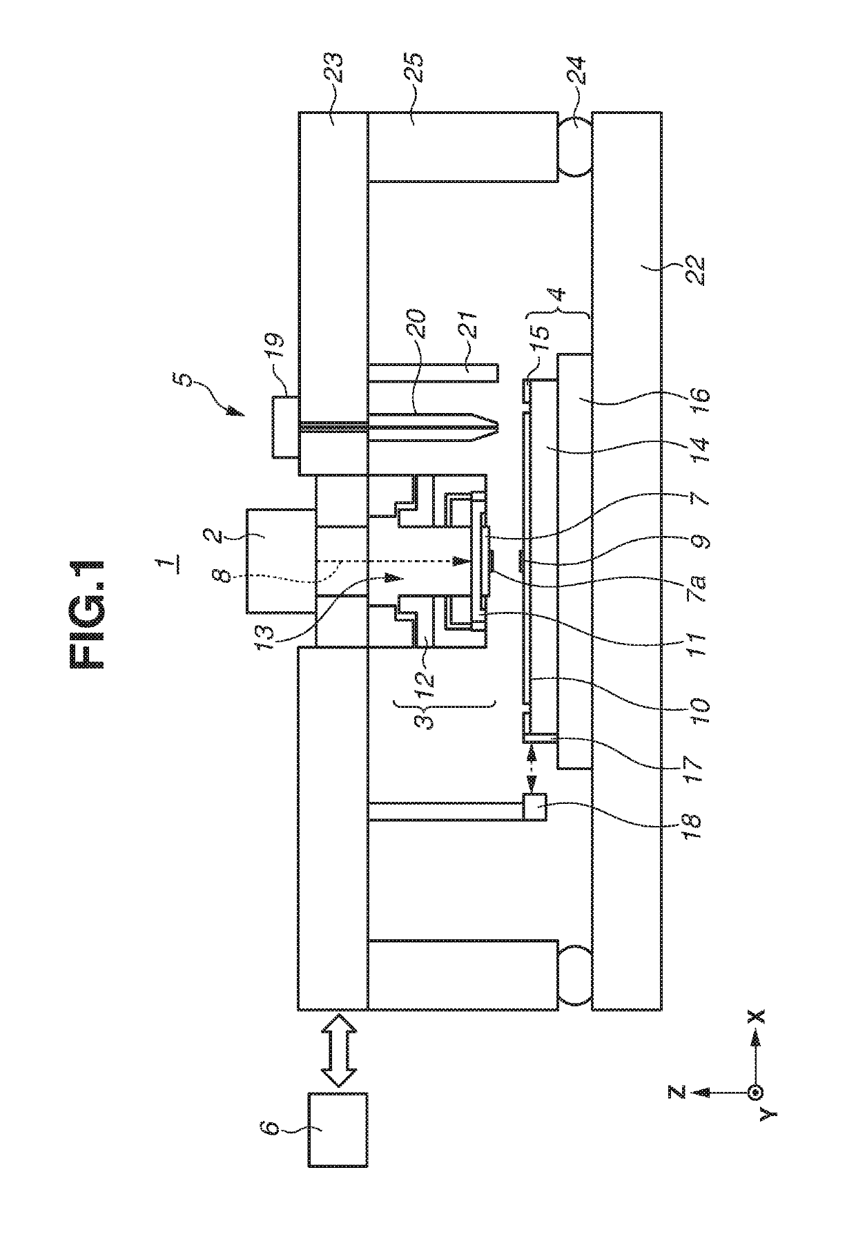
[0020]Hereinafter, the first exemplary embodiment will be described. FIG. 1 is a diagram illustrating an imprinting apparatus. An imprinting apparatus 1 (molding apparatus) brings an imprinting material (composite) 9 supplied onto a substrate 10 into contact with a mold (original or template) 7. Then, curing energy is applied to the imprinting material 9, so that a cured composite, onto which a concavo-convex pattern of the mold 7 is transferred, is molded.
[0021]Herein, a curable composite (also called an imprinting material to be cured) that is cured with application of curing e...
PUM
| Property | Measurement | Unit |
|---|---|---|
| Height | aaaaa | aaaaa |
| Composition | aaaaa | aaaaa |
| Area | aaaaa | aaaaa |
Abstract
Description
Claims
Application Information