Method and device for producing a winding element
- Summary
- Abstract
- Description
- Claims
- Application Information
AI Technical Summary
Benefits of technology
Problems solved by technology
Method used
Image
Examples
Embodiment Construction
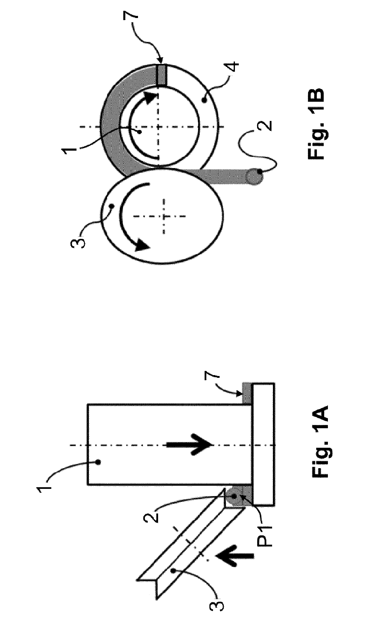
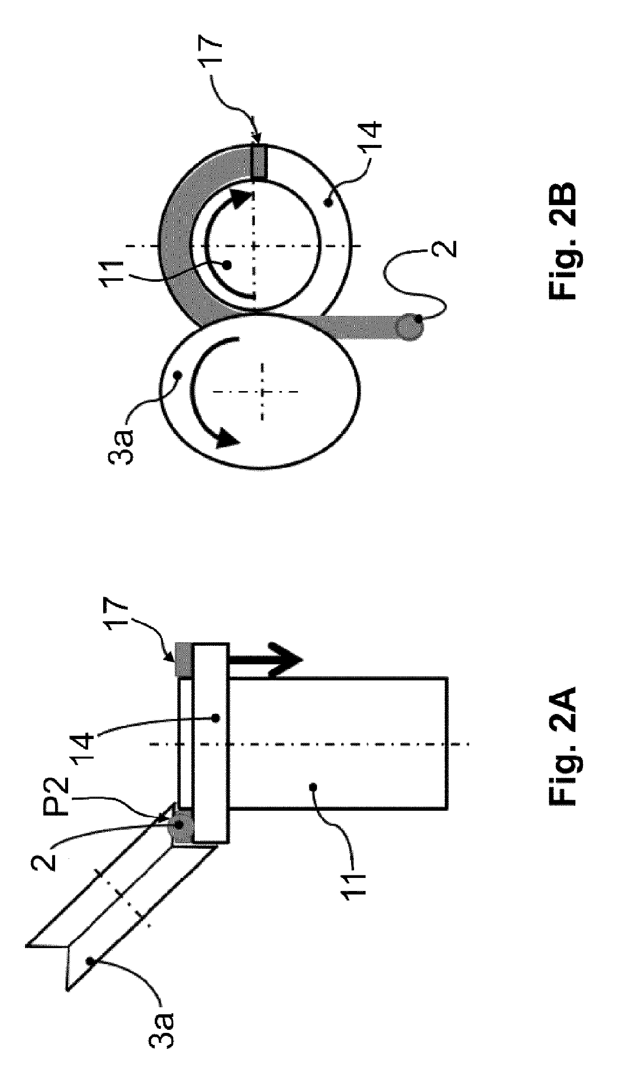
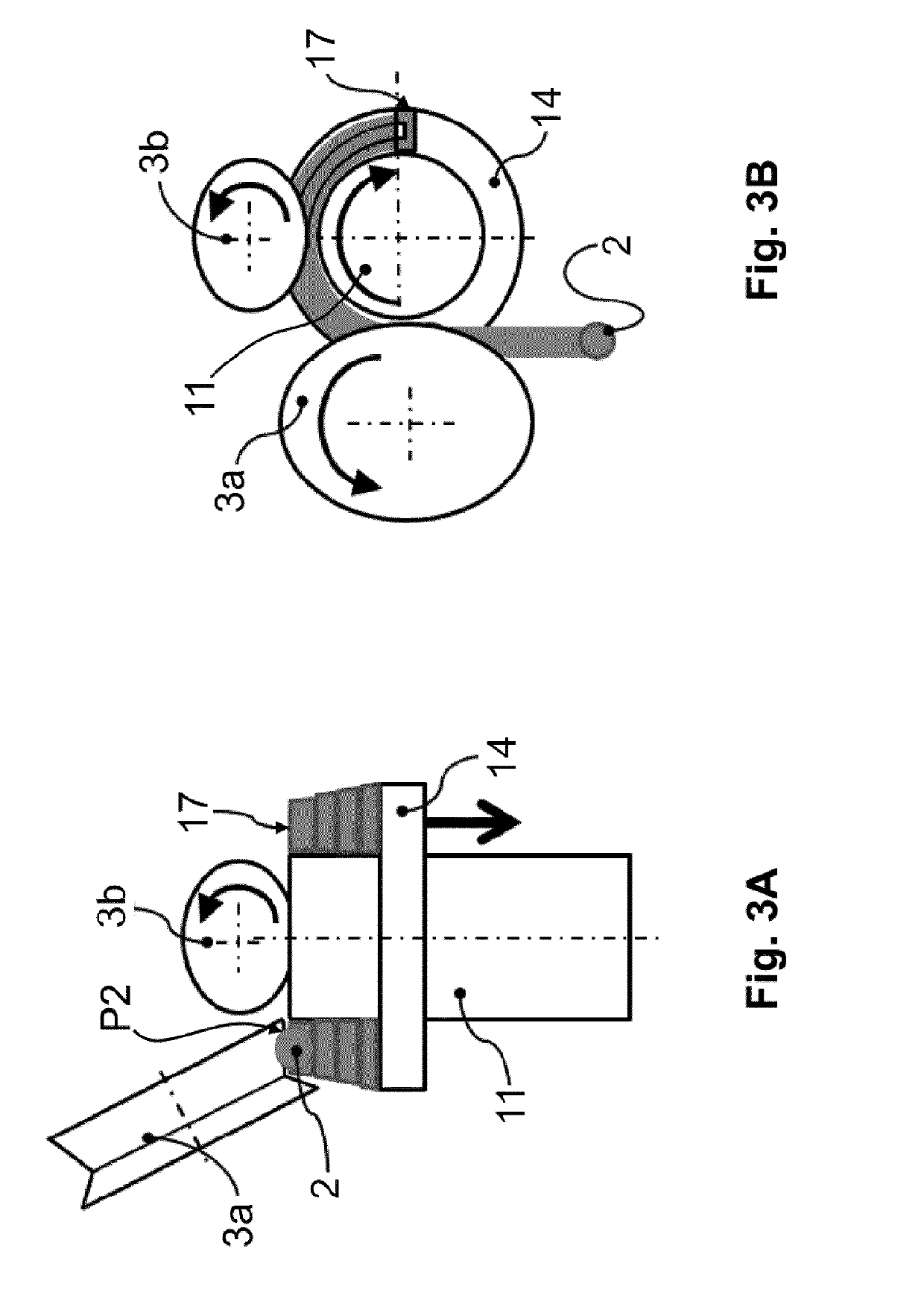
[0018]The approach illustrated in the embodiments of FIGS. 1A and 1B, 2A and 2B, 3A and 3B, 6 and 7 is to transform supplied wire 2 with respect to the cross section to a desired shape (e.g. trapezoidal shape) by use of a shaping tool (e.g., a section roller 3, 3a, 3b, 13) when winding wire 2 (in particular copper wire) with a round or otherwise shaped (e.g., oval or rectangular) initial cross section about a rotating mandrel 1, 11, 21, 31 which represents the interior of resulting winding element 7, 17, 27, 37.
[0019]The simultaneous winding of winding element 7,17, 27, 37 and cross-sectional deformation of supplied wire 2 can be achieved by the devices shown in the figures. A first device according to FIGS. 1A and 1B is shown in a side view and a top view perpendicular thereto. This device comprises a mandrel 1 on which a radially projecting fixed shoulder 4 is formed. Mandrel 1 and shoulder 4 are moved to rotate about their longitudinal axis during the winding process by a drive, ...
PUM
 Abstract
Description
Claims
Application Information
 - R&D
- Intellectual Property
- Life Sciences
- Materials
- Tech Scout
- Unparalleled Data Quality
- Higher Quality Content
- 60% Fewer Hallucinations
Browse by: Latest US Patents, China's latest patents, Technical Efficacy Thesaurus, Application Domain, Technology Topic, Popular Technical Reports.
© 2025 PatSnap. All rights reserved.Legal|Privacy policy|Modern Slavery Act Transparency Statement|Sitemap|About US| Contact US: help@patsnap.com


