Electric field radiation device and regeneration processing method

a technology of electric field radiation and processing method, which is applied in the direction of discharge tube main electrodes, x-ray tubes, x-ray tube cathode assemblies, etc., can solve the problems that guard electrodes etc. cannot properly undergo the regeneration process, and achieve the effect of suppressing the field emission of emitters and improving the characteristics of electric field radiation devices

Active Publication Date: 2019-11-07
MEIDENSHA ELECTRIC MFG CO LTD
View PDF0 Cites 1 Cited by
  • Summary
  • Abstract
  • Description
  • Claims
  • Application Information

AI Technical Summary

Benefits of technology

[0020]According to the present invention described above, it is possible to perform the regeneration process of the guard electrode etc. whi

Problems solved by technology

However, when the voltage of the regeneration process is merely applied across the guard electrode etc., field emission (e.g. field emission before performing th

Method used


Image

  • Electric field radiation device and regeneration processing method
  • Electric field radiation device and regeneration processing method
  • Electric field radiation device and regeneration processing method

Examples


embodiment 1

of Electric Field Radiation Device

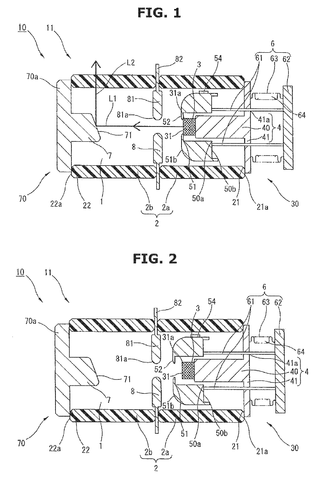
[0038]A reference sign 10 in FIGS. 1 and 2 is an example of an X-ray apparatus to which the electric field radiation device of the present embodiment 1 is applied. In this X-ray apparatus 10, an opening 21 at one end side of a tubular insulator 2 and an opening 22 at the other end side are sealed with an emitter unit 30 and a target unit 70 respectively (e.g. by brazing), and a vacuum enclosure 11 having a vacuum chamber 1 at an inner wall side of the insulator 2 is defined. Between the emitter unit 30 (an after-mentioned emitter 3) and the target unit 70 (an after-mentioned target 7), a grid electrode 8 that extends in a crossing direction of the vacuum chamber 1 is provided.

[0039]The insulator 2 is formed of insulation material such as ceramic. As the insulator 2, various shapes or forms can be employed as long as they can isolate the emitter unit 30 (the emitter 3) and the target unit 70 (the target 7) from each other and form the vacuum chamber ...

embodiment 2

of Electric Field Radiation Device

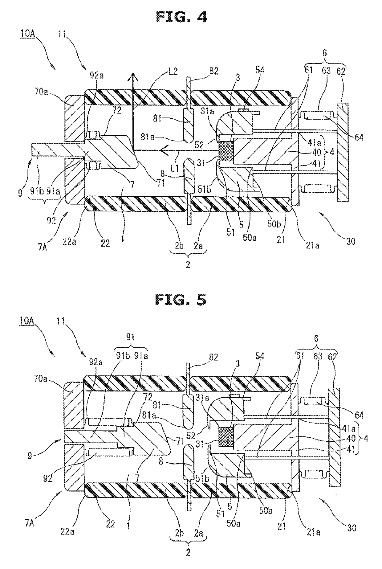
[0060]The X-ray apparatus 10 shown in FIGS. 1 and 2 has the guard electrode supporting unit 6. However, it is possible to employ a configuration, like an X-ray apparatus 10A as shown in FIGS. 4 and 5, in which the guard electrode supporting unit 6 and a target supporting unit 9 that supports the target 7 movably in the both end directions are provided. This configuration also has the same effect and working as those of the X-ray apparatus 10. Here, in FIGS. 4 and 5, the same element or component as that of FIGS. 1 to 3 is denoted by the same reference sign, and its explanation will be omitted below.

[0061]A target unit 7A of the X-ray apparatus 10A shown in FIGS. 4 and 5 has the target 7, the flange portion 70a and the movable target supporting unit 9 supporting the target 7 movably in the both end directions. As the target supporting unit 9, various shapes or forms can be employed as long as they can support target 7 movably in the both end directio...


PUM


Abstract

Emitter (3) and target (7) are arranged so as to face each other in vacuum chamber (1), and guard electrode (5) is provided at outer circumferential side of electron generating portion (31) of emitter (3). Guard electrode (5) is supported movably in directions of both ends of vacuum chamber (1) by guard electrode supporting unit (6). To perform regeneration process of guard electrode (5), guard electrode (5) is moved to opening (22) side (to separate position) by operating guard electrode supporting unit (6), and a state in which field emission of electron generating portion (31) is suppressed is set, then by applying voltage across guard electrode (5), discharge is repeated. After performing regeneration process, by operating guard electrode supporting unit (6) again, guard electrode (5) is moved to opening (21) side (to emitter position), and a state in which field emission of electron generating portion (31) is possible is set.

Description

TECHNICAL FIELD[0001]The present invention relates to an electric field radiation device and a regeneration processing method that are applied to various devices such as an X-ray apparatus, an electron tube and a lighting system.BACKGROUND ART[0002]As an example of the electric field radiation device applied to various devices such as the X-ray apparatus, the electron tube and the lighting system, there has been known a configuration in which voltage is applied between an emitter (an electron source formed of carbon etc.) and a target which are positioned (which are separated at a predetermined distance) while facing to each other in a vacuum chamber of a vacuum enclosure, an electron beam is emitted by field emission (by generation of electrons and emission of the electrons) of the emitter, and by colliding the emitted electron beam with the target, a desired function (for instance, in the case of the X-ray apparatus, a radioscopy resolution by external emission of X-ray) is obtain...

Claims


Application Information

Patent Timeline
IPC IPC(8): H01J35/06H01J35/16H05G1/02H01J35/12
CPCH01J2235/062H01J35/065H05G1/025H01J35/12H01J35/16H01J1/30H01J2235/064H01J35/066H01J35/112H05G1/02
Inventor TAKAHASHI, DAIZOTATSUMI, TOSHINORIHATANAKA, MICHIHIRO
Owner MEIDENSHA ELECTRIC MFG CO LTD
Why Eureka
Try Eureka