Water electrolysis reactor (SOEC) or fuel cell (SOFC) with an increased rate of water vapour use or fuel use, respectively

a technology of water electrolysis reactor and fuel cell, which is applied in the direction of fuel cells, electrochemical generators, electrical equipment, etc., can solve the problems of loss of yield, damage to the electrolyzer, and drop in yield, so as to reduce mechanical stress, increase the maximum degree of conversion, and ensure the effect of electrical continuity in the stack

Active Publication Date: 2019-11-14
COMMISSARIAT A LENERGIE ATOMIQUE ET AUX ENERGIES ALTERNATIVES
View PDF0 Cites 0 Cited by
  • Summary
  • Abstract
  • Description
  • Claims
  • Application Information

AI Technical Summary

Benefits of technology

This patent describes a seal arrangement for fuel cells and reactors that increases the effectiveness of gas distribution and reduces mechanical stresses on the cells. The seal is made of glass or glass-ceramic that is inserted into a porous metal screen. The seal prevents gas from leaking from the supply conduits to the non-active zones of the cell. The seal is crystallized at the operating temperatures of the reactor or fuel cell, preventing any further gas leakage. The structure allows for flexion of the cells in the stack without inducing a detrimental tensile mechanical stress. Overall, this seal arrangement improves the performance of fuel cells and reactors.

Problems solved by technology

B / good leaktightness between the two separate compartments, i.e. anode and cathode compartments, otherwise the gases produced will recombine, resulting in a drop in yield and in particular in the appearance of hot spots which damage the electrolyzer,
C / good distribution of the gases both at the inlet and on recovery of the gases produced, otherwise there will be a loss of yield, nonuniformity of pressure and nonuniformity of temperature within the various individual cells, or even unacceptable deterioration of the cells.
The high temperatures considerably complicate the fulfillment of the three abovementioned essential functions A / to C / .
In addition, the fragility of the solid oxide cells necessitates certain restrictive design measures so as to guarantee the mechanical integrity thereof.
Specifically, the second seal 7 becomes increasingly rigid over time, and the stresses applied to the stack result in tensile stresses due to this flexion which are damaging for each cell.
The drawbacks explained above have repercussions for all the individual units of the stack.

Method used


Image

  • Water electrolysis reactor (SOEC) or fuel cell (SOFC) with an increased rate of water vapour use or fuel use, respectively
  • Water electrolysis reactor (SOEC) or fuel cell (SOFC) with an increased rate of water vapour use or fuel use, respectively
  • Water electrolysis reactor (SOEC) or fuel cell (SOFC) with an increased rate of water vapour use or fuel use, respectively

Examples


Embodiment Construction

[0083]Other advantages and features of the invention will become more clearly apparent on reading the detailed description of examples of implementation of the invention, given by way of nonlimiting illustration with reference to the following figures, in which:

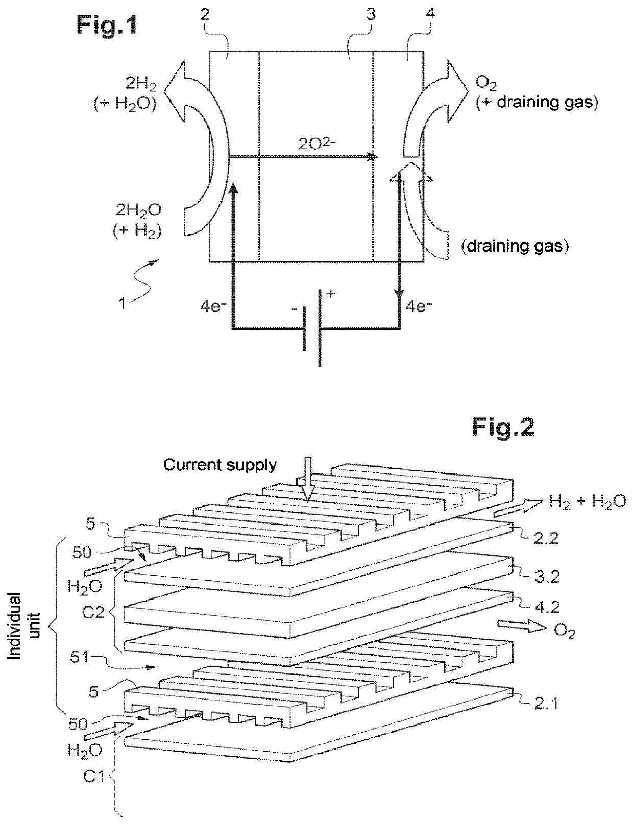
[0084]FIG. 1 is a schematic view showing the operating principle of a high-temperature water electrolyzer,

[0085]FIG. 2 is a schematic exploded view of a part of a high-temperature steam electrolyzer (HTE) of SOEC type comprising interconnectors according to the prior art,

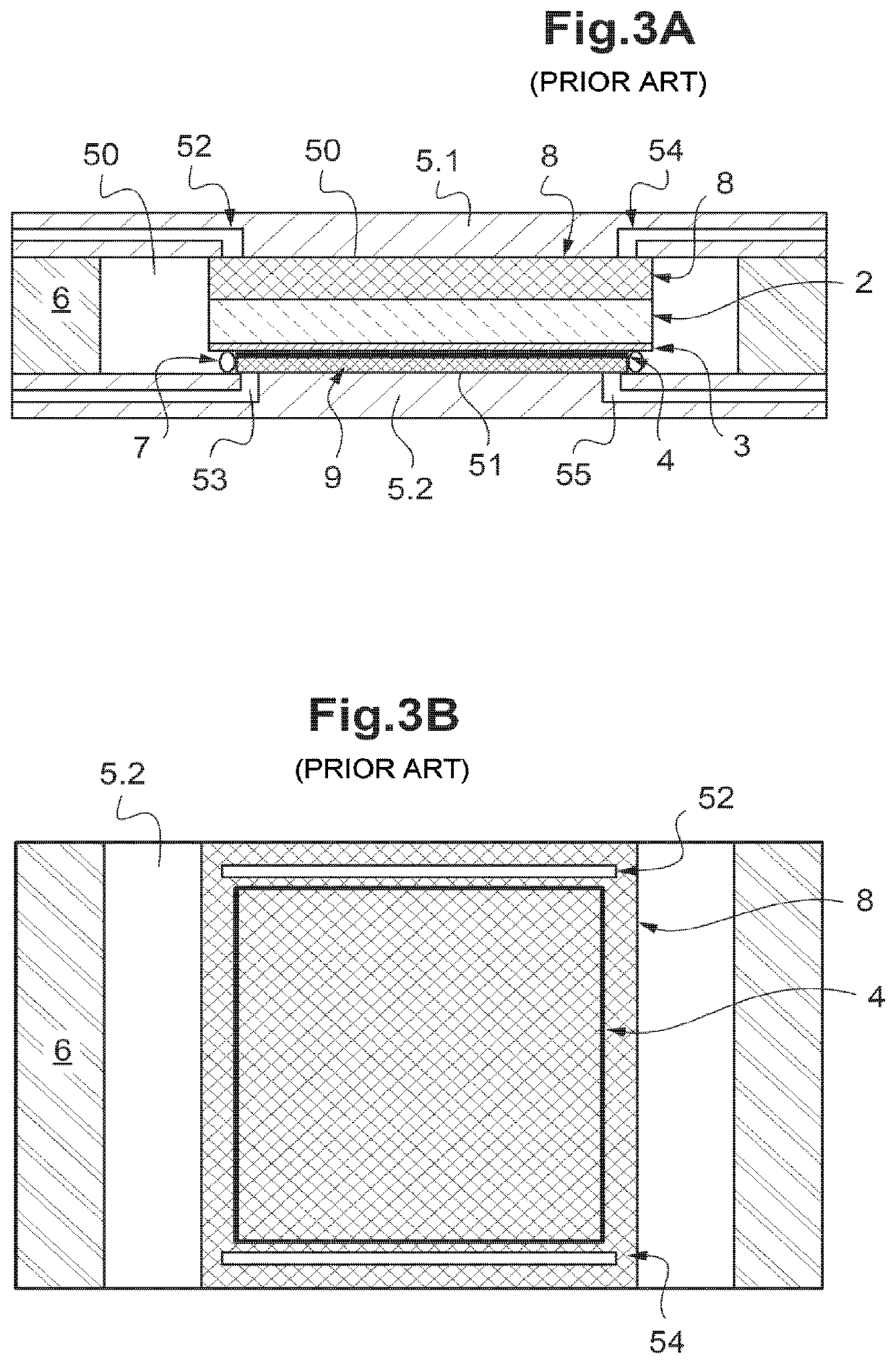
[0086]FIGS. 3A and 3B are respectively longitudinal cross-sectional and top schematic views of anindividual unit of an FITE electrolyzer or of a fuel cell of SOFC type according to the prior art showing the configuration of the seals, electrical contacts and distribution of gases within the stack,

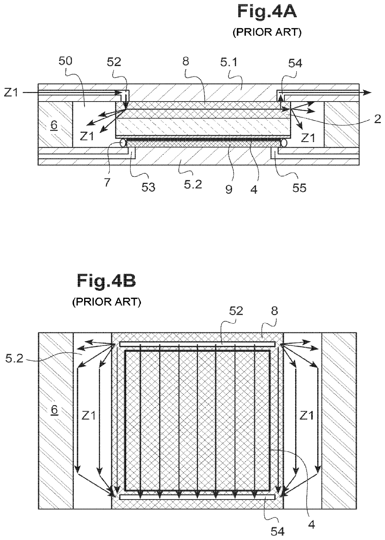
[0087]FIGS. 4A and 4B repeat FIGS. 3A and 3B and show the circulation of the steam and of the hydrogen produced, according to the prior art,

[0088]FIG. 5 is a view id...


PUM

PropertyMeasurementUnit
electron-conductingaaaaaaaaaa
heightaaaaaaaaaa
surface areaaaaaaaaaaa

Abstract

The invention relates to arranging a new seal within a porous substrate which forms the contact element of each hydrogen circulating electrode, such as the cathode for an SOEC reactor and the anode for an SOFC fuel cell, and in the periphery of the electrode beyond the ducts for supplying and recovering gases, in order to force the gases to circulate into the only useful zone of the cell which corresponds to the electrochemically active surface of the electrode. Thus, all of the gases supplied can be converted.

Description

TECHNICAL FIELD[0001]The present invention relates to the field of solid oxide fuel cells (SOFCs) and that of high-temperature electrolysis of water (HTE, acronym for “high-temperature electrolysis” or else HTSE, acronym for “high-temperature steam electrolysis”) or of co-electrolysis of steam and carbon dioxide CO2, also using solid oxides (SOEC, acronym for “solid oxide electrolysis cell”).[0002]The invention relates more particularly to a new design for the distribution of gases within a high-temperature water electrolysis or co-electrolysis (HTE) reactor of SOEC type, or a fuel cell of SOFC type, containing a stack of individual electrochemical cells, which makes it possible to attain high rates of use respectively of steam H2O or of fuel.[0003]Although it is described mainly with reference to the application of high-temperature water electrolysis, the invention also applies to an SOFC fuel cell supplied with hydrogen H2 and / or with methane CH4 as fuel, and with air or oxygen O2...

Claims


Application Information

Patent Timeline
Patent Type & Authority Applications(United States)
IPC IPC(8): H01M8/0273H01M8/1213H01M8/1231H01M8/2425H01M8/2457C25B1/10C25B15/08C25B9/04C25B9/18C25B9/23
CPCH01M8/0273H01M8/1231C25B9/18C25B9/04H01M2008/1293C25B15/08H01M8/1213C25B1/10H01M8/2457H01M8/2425H01M8/0286C25B1/00Y02E60/36Y02P20/129Y02E60/50C25B9/66C25B1/04C25B9/73C25B9/23C25B9/70C25B9/65
Inventor DI IORIO, STEPHANEROUX, GUILHEMORESIC, BRUNOREYTIER, MAGALI
Owner COMMISSARIAT A LENERGIE ATOMIQUE ET AUX ENERGIES ALTERNATIVES
Why Eureka
Try Eureka