Rotary seal and method of making same

Pending Publication Date: 2019-11-21
KALSI ENG
View PDF9 Cites 0 Cited by
  • Summary
  • Abstract
  • Description
  • Claims
  • Application Information

AI Technical Summary

Benefits of technology

This patent is about making better seals for high-difference pressure conditions by preventing the migration of elastomer onto critical surfaces of the seal during molding. A special seal shape and mold configuration are used to achieve this. The seals can have a machined surface that forms a circular external corner or a radially undulating external corner to reduce the area over which differential pressure can act. The technical effect is a longer seal life in high-difference pressure operating conditions.

Problems solved by technology

The manufacturing problem is caused by the relatively short and stiff axial portion of the plastic liner (30) that is located to the left of the inside corner (97).
As a result, the elastomer may inadvertently migrate to the wrong side of the plastic liner (30). which can lead to rejection of the part during inspection.
Such rejections add to the cost of molding the rotary seal (4).
A limitation of the manufacturing method described in the '146 Publication is the difficulty of fixturing the seal for the machining process.
Machining forces tend to drag the seal out of the fixture, resulting in a significant percentage of misshapen damaged seals that are unusable.

Method used


Image

  • Rotary seal and method of making same
  • Rotary seal and method of making same
  • Rotary seal and method of making same

Examples


Embodiment Construction

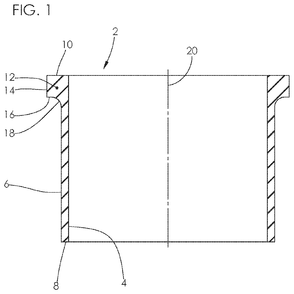
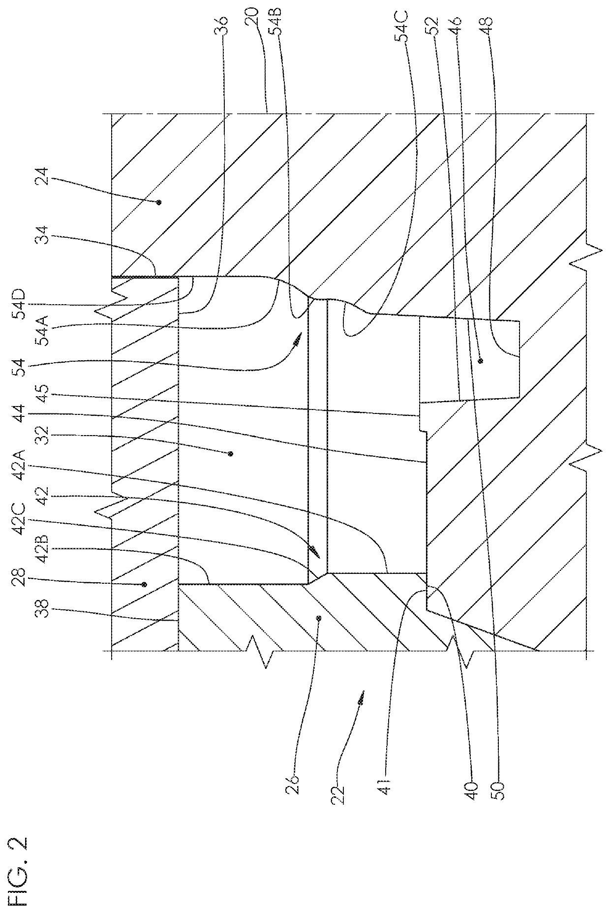
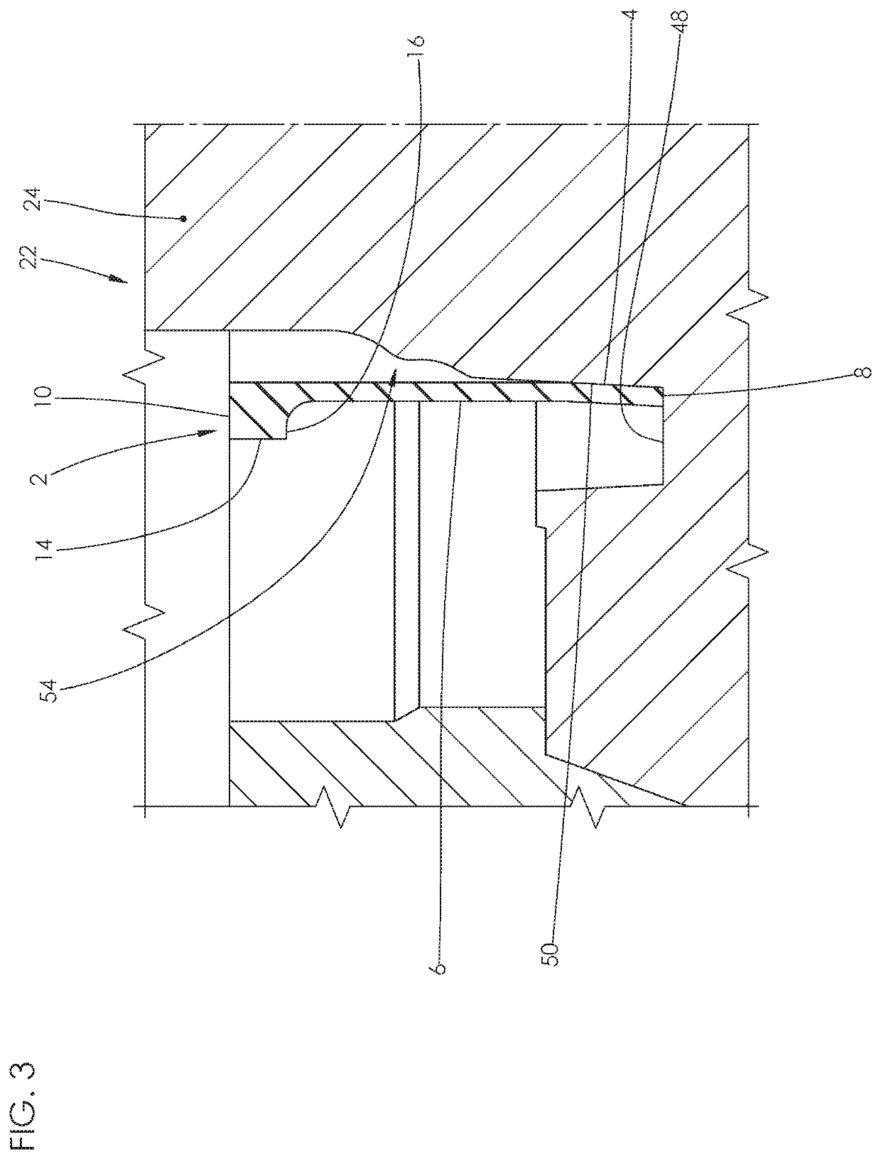
[0082]FIGS. 1 to 7 show a method for producing a rotary seal that overcomes the machining problems associated with the prior art. FIGS. 1-7 should be studied together, to gain a more complete understanding of the invention, because the totality of the invention cannot be perfectly conveyed by any single figure. Features throughout this specification that are represented by like numbers have the same function.

[0083]All the figures herein are longitudinal cross-section type illustrations that are intended to be interpreted by the standard conventions of sectional view orthographic drawing projection practiced in the United States.

[0084]Throughout this specification, the term “longitudinal cross-section” means a cross-section taken at a cutting plane that passes through and aligns with that theoretical axis; i.e., the theoretical axis lies on the cutting plane of the cross-section. The term “axis” is well-understood in mechanical engineering, and in the field of drafting is sometimes i...


PUM

PropertyMeasurementUnit
Pressureaaaaaaaaaa
Distanceaaaaaaaaaa
Environmental propertiesaaaaaaaaaa

Abstract

A seal configuration, mold and manufacturing process that inhibits undesirable elastomer migration onto critical radially inwardly facing portions of a plastic-lined dynamic sealing lip, for improved high-pressure seal operation.

Description

CROSS-REFERENCE TO RELATED APPLICATIONS[0001]This application claims the benefit of U.S. Provisional Application Ser. No. 62 / 762,703 filed on May 15, 2018, by Lannie L. Dietle and entitled “Seal Manufacturing Method.” Applicant incorporates by reference herein Application Ser. No. 62 / 762,703 in its entirety.BACKGROUND OF THE INVENTION1. Field of the Invention[0002]The present invention relates generally to rotary seals for establishing sealing between relatively rotatable machine components and separating a lubricant-type first fluid from a second fluid, where the geometry of the seal interacts with the first fluid during relative rotation to wedge a lubricating film into the dynamic sealing interface between the seal and a relatively rotatable surface.2. Description of the Related Art[0003]Assignee Kalsi Engineering, Inc. has patented and manufactured numerous hydrodynamic rotary seals over the years designed to accommodate various operating conditions. Typically, these hydrodynami...

Claims


Application Information

Patent Timeline
IPC IPC(8): F16J15/54F16J15/3208F16C33/80
CPCF16C33/805F16J15/3208F16J15/54F16J15/3284F16J15/328B29D99/0053B29C43/18F16J15/3236B29C43/38B29L2031/26B29C33/42B29C33/76
Inventor DIETLE, LANNIE L.
Owner KALSI ENG
Why Eureka
Try Eureka