Hybrid tactical rails with slow speed and high speed data buses

a technology of high-speed data and hybrid rails, which is applied in the direction of data switching current supply, data switching details, coupling device connections, etc., can solve the problem that the integration of data links is generally limited to low-speed data communication

Inactive Publication Date: 2019-11-21
SENSORS UNLTD +1
View PDF0 Cites 16 Cited by
  • Summary
  • Abstract
  • Description
  • Claims
  • Application Information

AI Technical Summary

Benefits of technology

[0010]A tactical rail arrangement includes an upper tactical rail as described above and a left or right tactical rail as described above. The non-contact optical connection of the upper tactical rail is arranged on the muzzle end of the upper tactical rail. The upper tactical rail includes first and second receiver end non-contact optical connections, the upper tactical rail high speed data spoke optically coupling the muzzle end non-contact optical connection to the first receiver end non-contact optical connection, and the high speed data spoke of the left or right tactical rail optically coupling the non-contact optical connection of the left or right tactical rail to the second receiver end non-contact optical connection.
[0011]In certain embodiments the low speed data bus segment of the left or right tactical rail can be electrically connected to the low speed data bus segment of the upper tactical rail. A high speed data user interface accessory can be electrically connected to the slow speed data bus segment of the upper tactical rail and the slow speed data bus segment of the left or right bus segment. The user interface accessory can be optically coupled to the first and second receiver end non-contact connections of the upper tactical rail.
[0012]In accordance with certain embodiments, the upper tactical rail can include a contact electrical connection co-located with the upper tactical rail receiver end non-contact optical connection. A contact electrical connection can be co-located with the upper tactical rail muzzle end non-contact optical connection. Two or more contact electrical connections can be arranged between the receiver end and the muzzle end of the upper tactical rail. The low speed data bus segment can electrically connect the contact electrical connection co-located with the upper tactical rail receiver end non-contact optical connection, the contact electrical connection co-located with the upper tactical rail muzzle end non-contact optical connection, and the two or more contact electrical connections arranged between the receiver end and the muzzle end of the upper tactical ra

Problems solved by technology

Integral data links are generally limited to low speed data communication, accessories requiring high speed data connectivity typicall

Method used


Image

  • Hybrid tactical rails with slow speed and high speed data buses
  • Hybrid tactical rails with slow speed and high speed data buses
  • Hybrid tactical rails with slow speed and high speed data buses

Examples


Embodiment Construction

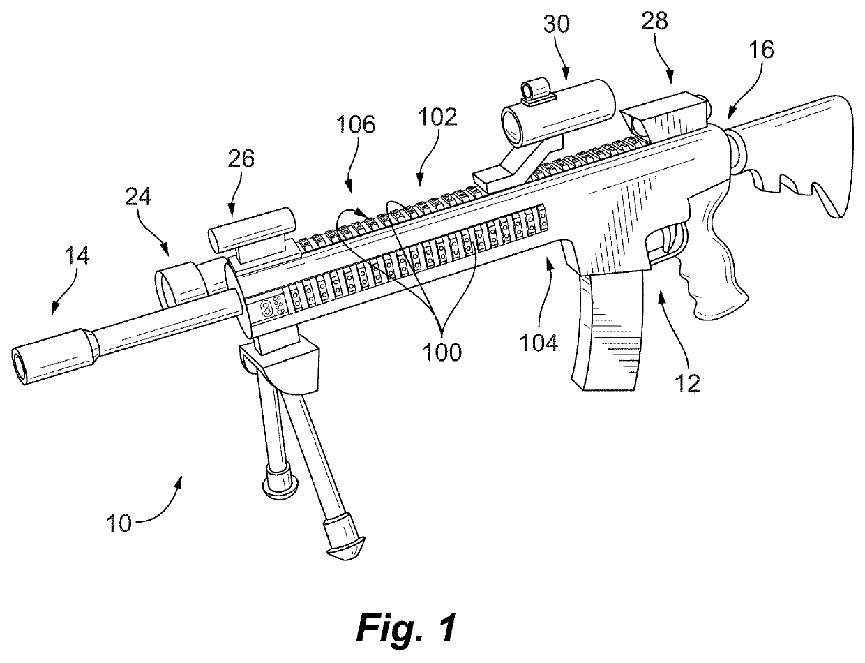
[0032]Reference will now be made to the drawings wherein like reference numerals identify similar structural features or aspects of the subject disclosure. For purposes of explanation and illustration, and not limitation, a partial view of an exemplary embodiment of a tactical rail arrangement in accordance with the disclosure is shown in FIG. 1 and is designated generally by reference character 100. Other embodiments of tactical rails, tactical rail arrangements, and firearm assemblies having tactical rails and tactical rail arrangements in accordance with the disclosure, or aspects thereof, are provided in FIGS. 2-17, as will be described. The systems and methods described herein can be used for providing connectivity for high speed data communication to firearm accessories, such as for imaging or video accessories, though the present disclosure is not limited to accessories requiring connectivity for high speed data communication in general.

[0033]Referring to FIG. 1, a firearm as...


PUM


Abstract

A tactical rail for a firearm includes a rail body having a receiver end and a muzzle end and a non-contact optical connection arranged at an end of the rail body and configured to interface with a corresponding non-contact optical interface. A low speed data bus segment extends between the receiver end and the muzzle end of the rail body. A high speed data spoke is connected to the non-contact optical connection for high speed data communication with a high speed data accessory through the non-contact optical connection and the corresponding non-contact optical interface. Tactical rail systems and firearm assemblies having tactical rails are also described.

Description

FEDERAL RESEARCH STATEMENT[0001]This invention was made with Unites States government support from the Department of the Army. The government has certain rights in the invention.BACKGROUND OF THE INVENTION1. Field of the Invention[0002]The present disclosure relates to firearms, and more particularly to firearm tactical rails with low speed and high speed data buses for accessories removably fixed to the tactical rail.2. Description of Related Art[0003]Firearms, such as assault rifles, commonly include accessory rails. Accessory rails generally conform to a rail standard, for example, MIL-STD-1913, Weaver, NATO STANAG 4694 accessory rails, and are designed to allow a user to attach and detach various accessories to firearms. Firearms fitted with accessory rails in turn can be readily kitted with various accessories that conform to the particular accessory rail standard, such as with telescopic sights, tactical sights, laser sighting modules, night vision devices, and range finders, ...

Claims


Application Information

Patent Timeline
IPC IPC(8): F41G11/00H01R13/24
CPCF41G11/003H01R13/2464F41C27/00H04B10/278H04L12/10H04L12/40
Inventor NEAL, HENRY WILLIAMSPROUL, MARK
Owner SENSORS UNLTD
Why Eureka
Try Eureka